Insertion Loss, Mismatch Loss, Transmission Loss
A correspondent asks about the effect of RCA connectors at HF on his proposed noise bridge. The question is very similar to that considered at Exploiting your antenna analyser #13 for UHF series connectors.
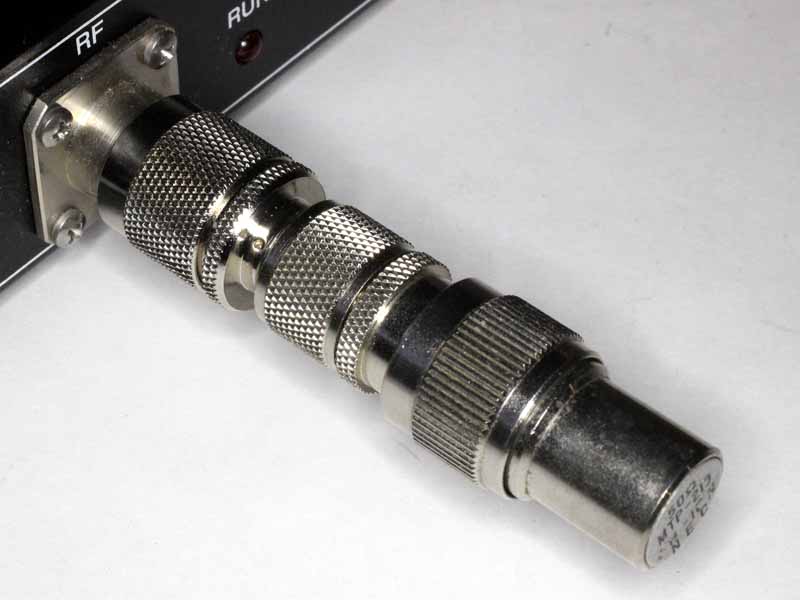
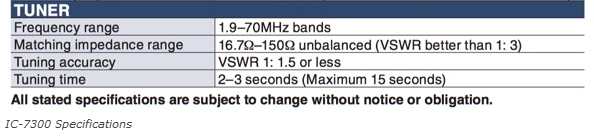
I have made a simple measurement of a BNC 50Ω termination (to check calibration) then inserted a BNC-RCA and RCA-BNC adapter.
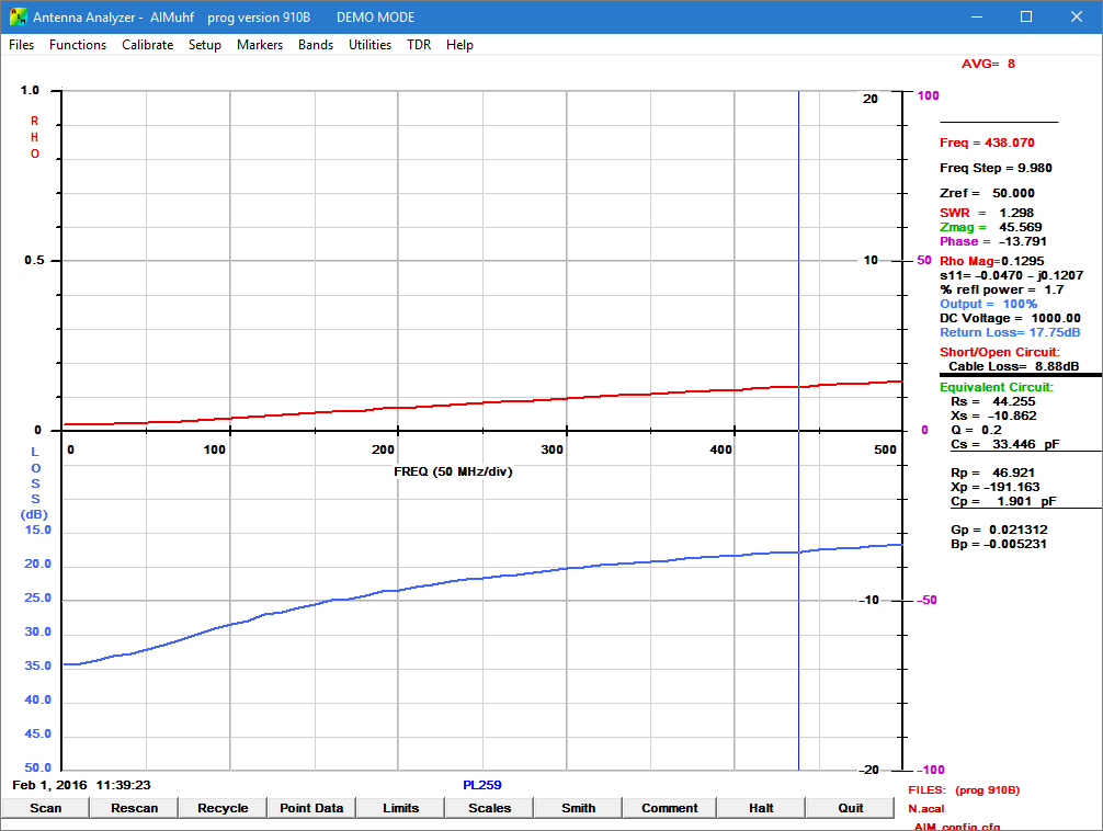
Measurements of input impedance only for such an electrical short transmission line will not give useful data for determining TransmissionLoss which is the result of conversion of RF energy to heat. The measurements do give ReturnLoss and given that InsertionLoss=MismatchLoss+TransmissionLoss, they set a lower bound for InsertionLoss.
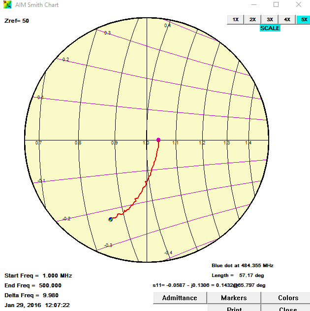
To jump to the chase, it also has a Smith chart plot up to 200MHz that suggests it might be well modelled by a TL segment of 30-35Ω.
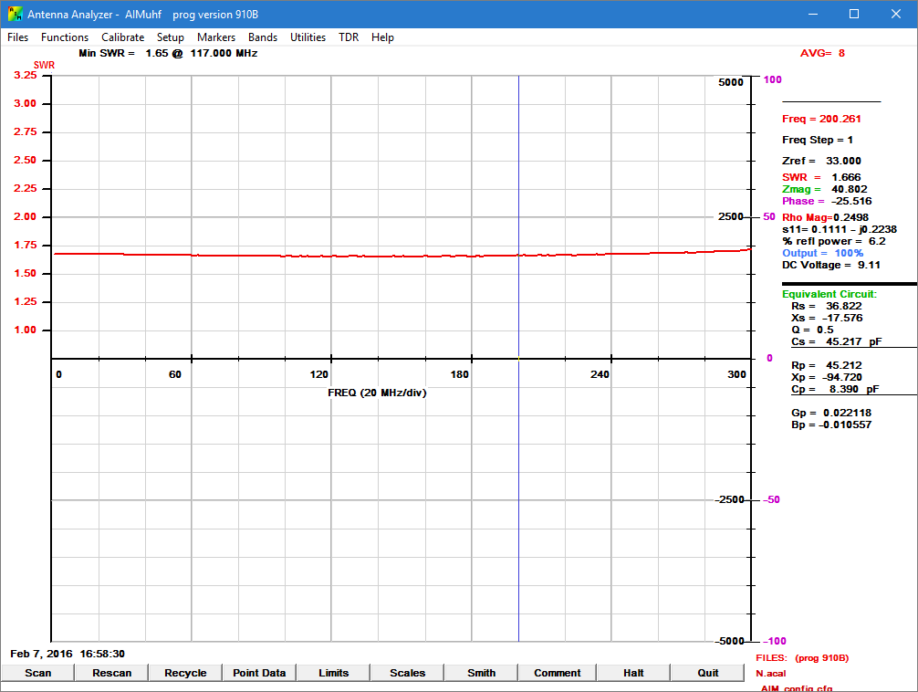
Above is a plot of VSWR when Zref is adjusted for the flattest response from DC, and it can be seen that with Zref=33, response is quite flat to 200MHz. Continue reading Exploiting your antenna analyser #14