A generic run on timer using an ATTINY25

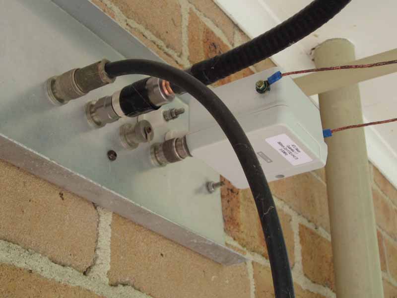
At Improved cooling for the MFJ-949E I described a modification to the ATU to improve its cooling using a fan and run on timer.

The run on timer described was based on a Chinese STC15F104E DIP8 8051 like microcontroller.

Because the programming tools for the STC chips work so poorly, and the lack of documentation of their protocol, there is no simple way to update only the calibration data in EEPROM. I have ported the algorithm to an ATTINY25 which doesn’t cost a lot more but had a much better development environment and a range of tools to allow EEPROM update without overwriting the FLASH image, and as well it will run my bootloader, ATB.

This article describes a generic run on timer based on an Atmel AVR chip, a ATTINY25 though the code will also run in ATTINY45 and ATTINY85.

ROT001

The circuit is very simple, the DC output from the forward power detector is connected to the input pin which turns the BC548C transistor on at input voltage greater than about 0.7V. The high value of base resistor ensures very light loading of the forward power detector.
Continue reading A generic run on timer using an ATTINY25

Design / build project: Guanella 1:1 ‘tuner balun for HF’ – #6

Sixth part in the series documenting the design and build of a Guanella 1:1 (current) balun for use on HF with wire antennas and an ATU.

This article documents measurement of impedance.

Impedance measurement

AEP01

The antenna system is a G5RV with tuned feeders (9m of home made 450Ω open wire). The tuned feeders terminate on the balun described in this series, and it is located on the outside of the antenna feed entrance panel shown above. Continue reading Design / build project: Guanella 1:1 ‘tuner balun for HF’ – #6

Design / build project: Guanella 1:1 ‘tuner balun for HF’ – #5

Fifth part in the series documenting the design and build of a Guanella 1:1 (current) balun for use on HF with wire antennas and an ATU.


Installation / testing

AtuBalun201

The balun packaged in a non-conductive housing was designed to have minimal stray capacitance to ground to minimise common mode current with asymmetric loads.

AEP01

Above, the balun is attached to the exterior side of the antenna feed entrance panel using a male to male N adapter, done up very tight. The feed line connections are liberally coated with marine grease to prevent ingress of water and oxygen, a measure to reduce corrosion. Continue reading Design / build project: Guanella 1:1 ‘tuner balun for HF’ – #5

Improved cooling for the MFJ-949E

vt_00032

At A look at internal losses in a typical ATU I demonstrated that it is quite easy to raise the temperature of the coil in the MFJ-949E to an unsafe level, even with quite modest power.

The most heat sensitive component in this ATU is the coil, specifically the coil supports which are probably polystyrene, and the melting temperature of polystyrene is around 100°.

This article documents modification of my MFJ-949E to reduce the risk of damage under some operating conditions. Continue reading Improved cooling for the MFJ-949E

A tutorial on initial design of operating conditions for a valve amplifier

A correspondent asked for a walk through of use of a couple of my online design tools for a 6m 350W single ended valve PA using three QQE06-40 valves. The request was perhaps inspired by a design he had seen, but I sound a caution about a large number of parallel valves (6 sections in this case).

Key design parameters:

  • HV power supply fully loaded: 1200V;
  • Power output: 350W;
  • Class: AB1;
  • Vak min: 180V (from datasheet anode curves);
  • Pi output network, Q at least 12 (for reduction of harmonics on the FM broadcast band), select 15.

The datasheet gives max supply voltage at 450 for plate and screen AM, which implies max ‘instantaneous’ DC supply voltage in AB1 SSB telephony of 900V… so 1200V goes beyond the guaranteed ratings. Of more concern, it is probably close to 1400V lightly loaded, 56% greater than the maximum instantaneous supply implied by the AM specifications.

Assumptions:

  • output network efficiency 90%;
  • valves load share equally.

An advantage of a high Q design is that it requires higher input C which makes accommodating the self capacitance of the 6 valve sections somewhat easier. A disadvantage is lower efficiency.

Screenshot - 12_03_16 , 16_21_24

Above is a calculation using Calculate initial load line of valve RF amplifier. Note the anode dissipation, a total of over 190W is quite high for 120W total valve rating (though these are pretty robust valves). Total DC anode current will be almost 0.5A, so the HV power supply must deliver 1200V @ 0.5A. The 0.5A figure is within the absolute maximum of 720mA (for 6 sections).
Continue reading A tutorial on initial design of operating conditions for a valve amplifier

Thinking about SOTA, EFHW and EMR safety

There seems to have been a revival in use of the so-called End Fed Half Wave antenna.

The prospect that a small radio such as the FT817, a magic match box and 10m of wire makes a good 20m field station appeals to many a SOTA enthusiast.

Let us model a scenario with a FT817 powered by internal battery and sitting on an insulating platform (eg a pack) 0.3m above natural ground, a 10m wire strung up into a tree at a 45° angle, and a 1m long mic cord stretched up at 45° in the other direction. The is the popular so-called ‘no counterpoise’ configuration.

A simplified model of just the current paths without regard to the bulk of the radio, or the effect of the helix of the mic cord illustrates an approximate current distribution. The model uses 1W RF input to the antenna over ‘average ground’ (σ=0.005, εr=13).


Clip 142

Above is a plot of the current distribution. Current is a minimum at the open ends, a boundary condition for the problem, and maximum in the middle of the half wave. We expect H field to be greatest near the current maximum, and E field to be greatest near the current minima. Continue reading Thinking about SOTA, EFHW and EMR safety

Design / build project: Guanella 1:1 ‘tuner balun for HF’ – #4

Fourth part in the series documenting the design and build of a Guanella 1:1 (current) balun for use on HF with wire antennas and an ATU.


Packaging

The prototype fits in a range of standard electrical boxes. The one featured here has a gasket seal (a weep hole would be advisable in a permanent outdoor installation).

AtuBalun201

Above, the exterior of the package with M4 brass screw terminals each side for the open wire feed line, and an N(F) connector for the coax connection. N type is chosen as it is waterproof when mated.

AtuBalun203

The interior shows the layout. The wires use XLPE high temperature, high voltage withstand, moderate RF loss insulation. Two short pieces of 25mm electrical conduit serve to position the balun core against the opposite side of the box, and a piece of resilent packing between lid and core holds the assembly in place.

AtuBalun202

Differently to the example shown in the earlier articles, this prototype uses twisted PTFE insulated wires which have voltage breakdown higher than the XLPE shown earlier.

Clip 124

The self resonant frequency of the built balun was measured as 7.4MHz and the predictive model above calibrated. The balun has high choking impedance on the lower half of HF.

Next installment: Design / build project: Guanella 1:1 ‘tuner balun for HF’ – #5.

Updated: Calculate initial load line of valve RF amplifier

Calculate initial load line of valve RF amplifier was written as a companion to my RF power amplifier tube performance computer tool to provide a starting point for building a model, but as it turns out, the initial load line (and related values) is a very good estimate and further modelling may not be needed.

Although written for an application to valves, it is quite applicable to any active device, keeping in mind that it assumes a linear transfer characteristic.

The update provides for both single ended and push-pull configurations.

For example, the requirement is for a single ended Class C bipolar amplifier to deliver 25W from a 13.8V DC supply. What is the ratio for a broadband output transformer to 50Ω.

Screenshot - 13_02_16 , 08_51_22

Above is the solution. The required Rl is 3.3Ω, and the required turns ratio is (50/3.3)^0.5=3.9. a 1:4 (turns) transformer would be selected for a prototype. Bear in mind that output power would fall to around 20W at 12V DC supply.

Another example is the common 100W 13.8V Class B push-pull design.

Screenshot - 13_02_16 , 09_22_26

With a requirement for around 3Ω collector to collector (or drain to drain), a transformer with 1:4 turns ratio would be selected.

Reconciling my #52 choke design tool with G3TXQ’s measurements

A correspondent wrote with concern of the apparent difference between graphs produced by my #52 choke design tool with a graph published by G3TXQ of his measurement of 11t on a pair of stacked FT240-52 cores.

I published a note earlier about my concerns with a similar graph by G3TXQ compared to the Fairrite datasheet, and he reviewed the data, found the error and published a corrected graph.

FT240-52x2-11t

The corrected graph above might at first glance appear different to my model’s graphs, and the first obvious difference is that G3TXQ uses a log Y scale (which is less common). The effect of the log scale is to compress the variation and give the illusion perhaps that in comparison with other plots, this balun has a broader response.

Screenshot - 09_02_16 , 18_29_42

To compare the two, I have roughly digitised G3TXQ’s graph above and plotted the data over that from my own model (with linear Y scale). Continue reading Reconciling my #52 choke design tool with G3TXQ’s measurements

Exploiting your antenna analyser #14

Insertion Loss, Mismatch Loss, Transmission Loss

A correspondent asks about the effect of RCA connectors at HF on his proposed noise bridge. The question is very similar to that considered at Exploiting your antenna analyser #13 for UHF series connectors.

I have made a simple measurement of a BNC 50Ω termination (to check calibration) then inserted a BNC-RCA and RCA-BNC adapter.

Measurements of input impedance only for such an electrical short transmission line will not give useful data for determining TransmissionLoss which is the result of conversion of RF energy to heat. The measurements do give ReturnLoss and given that InsertionLoss=MismatchLoss+TransmissionLoss, they set a lower bound for InsertionLoss.

To jump to the chase, it also has a Smith chart plot up to 200MHz that suggests it might be well modelled by a TL segment of 30-35Ω.

Screenshot - 07_02_16 , 16_58_55

Above is a plot of VSWR when Zref is adjusted for the flattest response from DC, and it can be seen that with Zref=33, response is quite flat to 200MHz. Continue reading Exploiting your antenna analyser #14