Logging temperature meter (ltm) v1 – a preview

Logging temperature meter (ltm) is a ESP8266 based temperature measurement and logging device.

The project is based on port of an existing ESP8266 Arduino project, and consideration was given to migration to the ESP32 hardware platform, but there are large differences to the WiFi related libraries… so for now, ESP8266 looks ok. There remain development options for multi channel logging if needed.

Design criteria

The design criteria are:

  • small, portable, battery powered;
  • direct reading temperature scale;
  • flexibility for a range of sensors;
  • local display including bar graph, time, and temperature;
  • log measurements to a serial port of some kind;
  • offer remote access for recent measurement log.

Algorithms

The initial algorithm implemented is for a negative temperature coefficient (NTC) thermistor using the single ADC port on the ESP8266. The code uses the Steinhart-Hart model to solve for temperature.

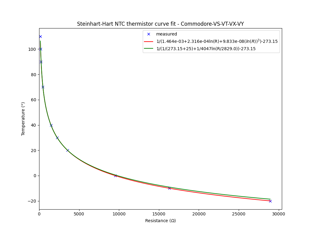
Above is a plot of the Steinhart-Hart model (red) and the so-called B equation (green) for the NTC used in my car. They are quite similar in this case, but the Steinhart-Hart model is more accurate. Continue reading Logging temperature meter (ltm) v1 – a preview

Engine coolant temperature sensors – a closer look

Diagnosis of engine coolant temperature gauge issue with a certain vehicle discussed ECT sensors in a specific context.

The following table of coefficients for four common sensors was derived from published measurements by TSD of a single sensor of each type.

The so-called B equation model is \(T=\frac{1}{\frac1{T_0}+\frac1Bln\frac{R}{R_0}}\).

Part R25 B25/100
AMR3321 2246 3897
ERR2081 2218 3879
ETC8946 2450 3671
AMR1425 536 4356

These are measurements of a single sample, so average values might be a little different. Additionally, the R25 / B25/100 model is only an approximation. Continue reading Engine coolant temperature sensors – a closer look

RK2672AM – calibration

The RK2672AM is a Chinese high voltage test set. This article describes a process for calibration of the device.

This process should not be attempted unless you have the requisite competencies, experience, tools and test equipment. There are dangerous voltages involved, so assess the hazards, plan your work, don’t attempt it if fatigued or alcohol enhanced.

Above is the front panel of the RK2672AM. Continue reading RK2672AM – calibration

Diagnosis of engine coolant temperature gauge issue with a certain vehicle

The subject vehicle is a Land Rover Defender of mixed heritage. The owner describes the engine coolant temperature (ECT) gauge as useless.

The ECT display system is a dashboard gauge and negative temperature coefficient (NTC) thermistor mounted near the engine thermostat. It measures the engine coolant temperature (hence its name) at the hottest point in the coolant circuit… so it gives the best warning that coolant might be approaching boiling point… and which point cooling capacity catastrophically falls and there is a significant risk of permanent engine damage.

It would seem that Land Rover used many different dashboard gauges, but the underlying electrical characteristics were of just two different types. Likewise there appears to be several different sensors.

The following table of coefficients for four common sensors was derived from published measurements by TSD of a single sensor of each type.

Part R25 B25/100
AMR3321 2246 3897
ERR2081 2218 3879
ETC8946 2450 3671
AMR1425 536 4356

These are measurements of a single sample, so average values might be a little different. Additionally, the R25 / B25/100 model is only an approximation. Continue reading Diagnosis of engine coolant temperature gauge issue with a certain vehicle

A handy 230VAC 10A inline power meter based on an inexpensive module from eBay

This article describes a simple and inexpensive inline power meter for use as a test instrument.

CNC routing

The box cutouts were done on a CNC router, but they could be done with hand tools.

Above, calcs of feeds and speeds for the CNC router. The box is actually ABS, but cutting speed for Polycarbonate is the same.

Above is the tool path for one side of the box. The cutouts suit the 7P-2 strain reliefs. The gcode is generated from a custom Python file using a custom library of common shapes that I use. Continue reading A handy 230VAC 10A inline power meter based on an inexpensive module from eBay

Return Loss Bridge – some woolly thinking – a Simsmith model of a reflection bridge

Return Loss Bridge – some woolly thinking discussed some online opinions on the practical measurement range of nanoVNA, and underlying reasons… but both were flawed.

Reflection Bridge and Return Loss Bridge are somewhat synonymous, in practice to measure Return Loss one is interested in the magnitude of the response, and to measure the complex reflection coefficient or s11, both magnitude and phase are of interest.

He derives a flawed expression for bridge response, then plots a dodged up version to demonstrate the asymmetry of the response.

Above is Oristopo’s graph. Continue reading Return Loss Bridge – some woolly thinking – a Simsmith model of a reflection bridge

Return Loss Bridge – some woolly thinking

Some discussion on groups.io nanovna-users attempts to explain the behavior of the RF Return Loss Bridge used in some VNAs and other instruments, proof if you will that the instruments are not capable of measuring more than a few hundred ohms.

Oristopo gives a diagram and explanation.

Above is his diagram. He gives an expression that he states applies when R1=R3=R4=Rm: im = sqrt(Vf*(Rm – R2)/(12*Rm + 4*R2)). Continue reading Return Loss Bridge – some woolly thinking

On Insertion Loss

Readers of my articles occasionally ask for explanation of the distinction between meanings of:

  • Insertion Loss;
  • Mismatch Loss;
  • Loss (or Transmission Loss).

These terms apply to linear circuits, ie circuits that comply with linear circuit theory, things like that impedances are independent of voltage and current, sources are well represented by Thevenin and Norton equivalent circuits.

Insertion Loss

Insertion Loss is the ratio of power into a matched load (to mean that the load impedance is the complex conjugate of the Thevenin equivalent source impedance) to the power in the load with the subject network / device inserted.

Insertion Loss can also be expressed in dB.

Mismatch Loss

Mismatch Loss is the ratio of output power of a source into a matched load to the output power under a given mismatch.

Mismatch Loss can also be expressed in dB.

Loss

Loss is simply \(\frac{Power_{in}}{Power_{out}}\).

Loss can also be expressed in dB.

Loss is sometimes called Transmission Loss to distinguish it from other qualifications, but it is unnecessary. Recent hammy Sammy practice is to label |s21| graphs Transmission Loss which is an error on two counts.

Let’s illustrate these with some examples using Simsmith. Whilst these are models, you would expect to measure similar results using a good VNA or like test equipment. Continue reading On Insertion Loss

Fair-rite’s ‘new’ #43 permeability data (2020)

Fair-rite publishes spreadsheets of the complex permeability characteristic of many of the ferrite mixes. This note is about #43 mix and clarification I sought from Fair-rite.

Question

I note that recently, the published table of #43 permeability changed subtly but significantly. Does this table apply to historical product, or does it only apply to new product, ie was there an actual change in the mix, or what it the result of better measurement of characteristics?

Continue reading Fair-rite’s ‘new’ #43 permeability data (2020)

A DIY thermostat based on the MS1230A controller

This article documents the build of a DIY thermostat based on an inexpensive ($12) Chinese temperature controller.

Controller module

The controller used is a 220VAC MH1230A.

Above is an internal view of the controller. Importantly it has a relay rated at 240V 30A, and 15A at PF=0.4. The datasheet rates the relay for a 2HP (1.5kW) motor. It uses a ‘conventional’ power supply, the brown component is the power transformer. Most similar products use inadequate relays and have low grade switched mode power supplies that create RF noise. Continue reading A DIY thermostat based on the MS1230A controller