A common scheme for narrow band match of an end fed high Z antenna – surely it is a 1:9 transformer?

A reader of A common scheme for narrow band match of an end fed high Z antenna commented:

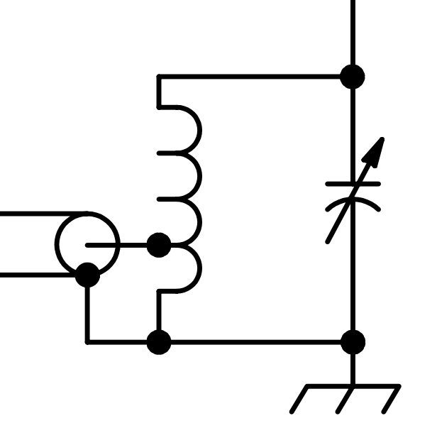
…if the coil is tapped at 1/3, surely then the coil is a 1:3^2 or 1:9 transformer and the capacitor simply ‘tunes out’ the coil reactance, what is the input impedance when it has a 450+j0Ω load?

That is very easy to calculate in the existing Simsmith model.

Above, with load of 450+j0Ω, the input impedance at 50MHz is 8.78+j34.36Ω (VSWR50=8.4), nothing like 50+j0Ω. Continue reading A common scheme for narrow band match of an end fed high Z antenna – surely it is a 1:9 transformer?

A common scheme for narrow band match of an end fed high Z antenna

This article discusses the kind of matching network in the following figure.

A common variant shows no capacitor… but for most loads, the capacitance is essential to its operation, even if it is incidental to the inductor or as often the case, supplied by the mounting arrangement of a vertical radiator tube to the mast. Continue reading A common scheme for narrow band match of an end fed high Z antenna

Differences in two similar simple untuned small loop configurations

A correspondent asked about the difference between two small untune loops mentioned in two of my articles, this article explains.

Firstly lets set the context, a small loop means less than λ/10 perimeter, and untuned is to mean that the loop is loaded directly, in this case by a receiver which we will assume has an input impedance of 50+j0Ω.

Let’s look at the two cases. The key difference is in the connection at the gap:

  • the first has a short circuit coaxial stub of half the perimeter between the inner conductor at the right side of the gap and the outer surface of the outer conductor at the right side of the gap; and
  • The second directly connects the inner conductor at the right side of the gap and the outer surface of the outer conductor at the right side of the gap.

Small single turn un-tuned shielded loop

Above is a diagram of the loop. Continue reading Differences in two similar simple untuned small loop configurations

Shorting winding sections of a ferrite cored EFHW transformer

A chap recently posted some advice on construction of a dual ratio transformer for EFFHW antennas, advice with an informative pic, but without measurement evidence that it works well.

Pictured is a dual UnUn. I made this for experimenting. It’s both a 49 and 64 to 1 UnUn.

The 49 to 1 tap uses the SS eye bolt for the feed through electrical connection and the SS machine screw on the top is the 64 to 1 connection. If I want to use the 49 to 1 ratio, there’s a jumper on the eye bolt that connects to the top machine screw where the antenna wire is attached. The jumper shorts out the last two turns of the UnUn. Disconnect the jumper from the top connection and now you have a 64 to 1 ratio.

Continue reading Shorting winding sections of a ferrite cored EFHW transformer

N6THN’s novel balun – flux leakage

N6THN’s novel balun presented measurement of the Insertion VSWR of the subject balun, and N6THN’s novel balun – an explanation gave explanation that included mention of flux leakage as a contributor to the quite high inductance per unit length of the transmission line formed by the two windings.

A correspondent suggested that with a ferrite core, flux leakage is insignificant. This article calculates the coupled coils scenario.

The balun as described

Above is the ‘schematic’ of the balun. Note the entire path from rig to dipole. Continue reading N6THN’s novel balun – flux leakage

N6THN’s novel balun

One sees lots of articles and videos on how to make a current balun suited to a low VSWR antenna. This one was recommended in an online discussion on QRZ.com. N6THN might not have invented this balun, but he made a video of it.

In this case, it is described in the referenced video as part of a half wave dipole antenna where you might expect the minimum feed point VSWR to be less than 2.

Apologies for the images, some are taken from the video and they are not good… but bear with me.

The balun as described

Above is the ‘schematic’ of the balun.Note the entire path from rig to dipole. Continue reading N6THN’s novel balun

Comment on KN5L on balun CMRR – series through impedance fixture

In recent articles, I flagged that on some of John’s VNWA plots he showed flawed impedance calculations using VNWA’s t2s inbuilt function.

The function t2s is documented in the VNWA help.

t2s is a VNWA built in function intended to solve the so-called s21 series through fixture for impedance measurement of two terminal Zx connected between Port 1 and Port 2.

None of John’s test fixtures were equivalent to the circuit above required for valid t2s transformation. Continue reading Comment on KN5L on balun CMRR – series through impedance fixture

Comment on KN5L on balun CMRR – two wire line example

The article Comment on KN5L on balun CMRR dealt with model and measurement of John’s coaxial choke in fixture, dealt with first because it is a simpler model. This article builds on that and models the balun wound with a pair of wires.

Above is the subject balun in fixture.

John’s schematic shows the balun as coupled coils, but that does not capture the transmission line transformation that occurs in the actual device. Again the test fixture is used without explanation. Continue reading Comment on KN5L on balun CMRR – two wire line example