A simplified design for small broadband RF transformers using medium µ ferrite core for receiving use.
The characteristic of typical medium µ ferrite mixes, particularly NiZn, are well suited to this application.
This article continues with the design discussed at BN43-2402 balun example, but using a 4t primary and 12t secondary for a nominal 1:9 50:450Ω transformer.
Lets consider a couple of simple starting points for low end and high end rolloff.
Low end roll off
A simple model for these devices with low flux leakage is an ideal transformer with primary shunted by the magnetising impedance. To obtain low InsertionVSWR, we want the magnetising impedance in shunt with 50+j0Ω to have a low equivalent VSWR.
Typically complex permeability changes in-band, and although it tends to decrease, increasing frequency means that the critical point for magnetising impedance is the low end.
High end roll off
At the high end, transformation departs from ideal usually when the length of wire in a winding exceeds about 15°.
Going forward
A small core makes for short windings to obtain high frequency performance, and sufficient turns are needed for low end… but not too many as it restricts the high end.
There are lots of rules of thumb for minimum magnetising impedance, most treat the inductor as an ideal inductor and these ferrites are not that.
A quick analysis using the method in BN43-2402 balun example hints that a 4t primary is probably good enough down to 1.8MHz, depending on one’s limit for InsertionVSWR. We are not being too fussy here… this is not an application that demands InsertionVSWR < 1.2.

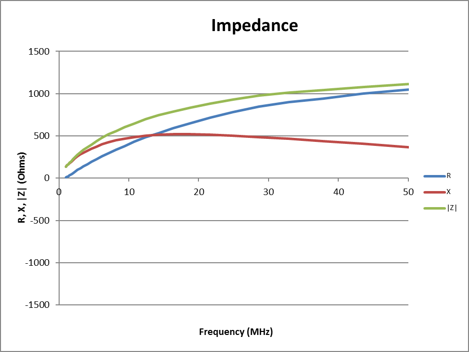
Above is a plot of expected R and X for a 4t winding using my common mode choke design tool. Z at 1.8MHz is 49+j199Ω, or Y=0.00117-j0.00474S. (If your design tools are not giving you similar values, you might consider validating them.) Adding the shunt 50Ω (Y=0.02), we get Yt=0.02117-j0.00474S, and plugging that in to calculate VSWR… Continue reading A method for design of small broadband RF transformers using medium µ ferrite core for receiving use
Last update: 30th July, 2018, 11:36 AM
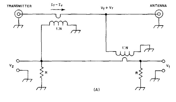
 Above is the directional coupler part of the MFJ-993B. The REF test point is designed to present voltages within the range 0-5V when used within the stated power ratings. Continue reading Reflected power alarm for the MFJ-993B