In testing RC electric drive systems (ESC + BLDC motor), a repeatable scenario was needed to evaluate changes such as changes to commutation advance.
Often these changes have different impact under rapid acceleration or deceleration to slower changes.
This article describes a simple servo signal ramp generator based on Arduino hardware, in this case using an Arduino Nano but most Arduinos or clones could be used or adapted.
The method used here does not make permanent hardware changes to the Nano. The firmware is compiled in the Arduino workbench and loaded onto the Nano using the USB FTDI interface. The signal to the ESC is taken from the pin ISP connector using an adapter cable fabricated from a servo extension cable with the female end (meaning with female pins) replaced with a 2×3 IDC header plug.

Above shows the standard Nano board with 9 pin ISP header installed, and the adapter cable. Note the IDC header plug picks up the white, red and black wires on pins 1, 2 and 6.
The Nano is powered from the servo cable, and the firmware starts a timer when power is applied to the system, and after a programmable delay starts the up ramp and down ramp.
An eLogger4 was used to capture voltage, current, servo, and rpm.
Another cycle is initiated by repowering the system, which also triggers a new recording session in the eLogger4.
The captured data can be downloaded and analysed.
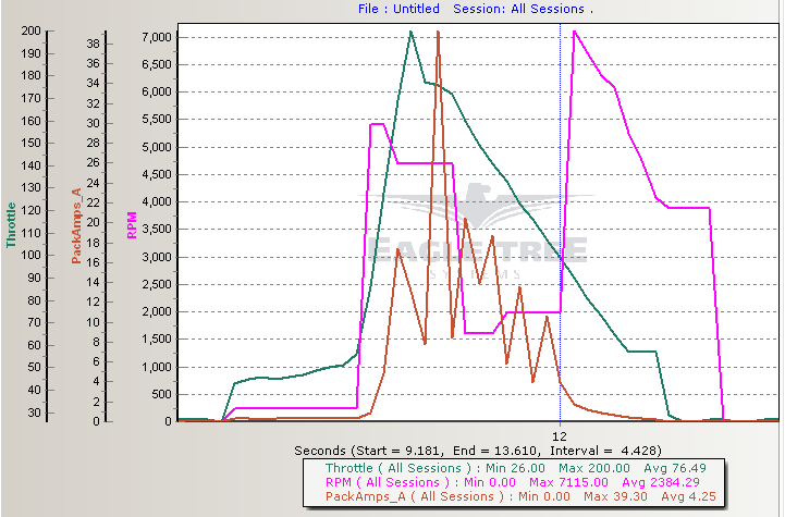
Above shows capture of a drive system where the ESC loses sync with the motor.
Here is the code.
/*
  Servo ramp generator
  Copyright: Owen Duffy 2013. All rights reserved.
 */
#include <math.h> //known bug in delay()
#define SERVOUT 12
#define LED 13
#define RATE 100
volatile int pw=1000;
volatile int pwn=0;
volatile int pwi=0;
int i,j;
char sel;

//=================================================================================================
//this routine sets up loop variable for the int handler to send incn increnents of inc value
//then waits until there are no more increments to be applied.
void ramp(int inc,int incn){
  cli();
  pwi=inc;
  pwn=incn;
  sei();
  while(pwn); //wait until request done
}
//=================================================================================================
void setup() {
pinMode(SERVOUT, OUTPUT);
digitalWrite(SERVOUT,0);

cli();//disable interrupts while we set things up
//set timer1 interrupt
TCCR1A=0;
TCCR1B=(1<<WGM12)|(1<<CS12);// Set CTC mode, CS12 bit for 256 prescaler
// set compare match register for 50Hz, 20ms update rate
OCR1A=F_CPU/(256*RATE)-1 ;
// enable timer compare interrupt
TIMSK1|=(1<<OCIE1A);
GTCCR|=(1<<PSRSYNC);// reset the prescaler
TCNT1=0;
PORTD=0xf0;


sei();//enable interrupts, start servo signal
//signal starting up
digitalWrite(LED,1);
delay(1000);
for(i=3;i--;){
  digitalWrite(LED,0);
  delay(500);
  digitalWrite(LED,1);
  delay(500);
  }

//now run the tests
sel=(~PIND&0xf0)>>4;
switch(sel){
case 0:
  ramp(100/(RATE*0.02),RATE*0.02); //quick start to idle
  delay(1000);

  //Simon's jump test 100ms @ 1900, instant jump
  ramp(800,1); //instant up to 1900
  delay(100);
  ramp(-800,1); //instant down to 1100
  delay(1000);

  //restart test
  ramp(200/(RATE*0.1),RATE*0.1); //quick up to 1300
  for(i=3;i--;){
    ramp(-300/(RATE*0.05),RATE*0.05); //quick down to 1000
    delay(40);
    ramp(300/(RATE*0.05),RATE*0.05); //quick up to 1300
    delay(2000);
    }
  ramp(-200/(RATE*0.1),RATE*0.1); //quick down to 1100

  //rapid mid range test
  ramp(300/(RATE*0.05),RATE*0.05); //quick up to 1400
  for(i=5;i--;){
    ramp(200/(RATE*0.05),RATE*0.05); //quick up to 1600
    delay(50);
    ramp(-200/(RATE*0.05),RATE*0.05); //quick down to 1400
    delay(50);
    }
  ramp(-300/(RATE*0.1),RATE*0.1); //quick down to 1100
    delay(2000);

  //other tests
  ramp(900/(RATE*2),RATE*2); //slow up ramp to max
  delay(500);
  ramp(-150/(RATE*0.5),RATE*0.5); //quick down to 1850
  delay(500);
  for(i=3;i--;){
    ramp(-650/(RATE*0.5),RATE*0.5); //quick down to 1200
    ramp(650/(RATE*0.5),RATE*0.5); //quick up to 1850
    ramp(-250/(RATE*0.2),RATE*0.2); //quick down to 1200
    ramp(250/(RATE*0.2),RATE*0.2); //quick up to 1850
    ramp(-850/(RATE*0.5),RATE*0.5); //quick down to 1000
    ramp(400/(RATE*0.2),RATE*0.2); //quick up to 400
    delay(500);
    ramp(450/(RATE*0.2),RATE*0.2); //quick up to 1850
    delay(1000);
    }

  ramp(-750/(RATE*2),RATE*2); //slow down to 1100 (idle)
  delay(2000);
  ramp(-100/(RATE*0.5),RATE*0.5); //quick down to 1000 (stop)
  break;
case 1:
  //ramp(100/(RATE*0.02),RATE*0.02); //quick start to idle
  delay(1000);

  for(i=10;i--;){
    ramp(100/(RATE*0.02),RATE*0.02); //
    delay(4000);
  }
  ramp(-1000/(RATE*0.02),RATE*0.02); //
  break;
}
digitalWrite(LED,0); //all over
}
//=================================================================================================
ISR(TIMER1_COMPA_vect){
  //send servo signal
  digitalWrite(SERVOUT,1);
  delayMicroseconds(pw-3);
  digitalWrite(SERVOUT,0);
  //update loop
  if(pwn){
    pw+=pwi;
    pwn--;
    }
}
//=================================================================================================
void loop() {
}
//=================================================================================================
The code uses the high four bits of PIND to select the test scenario. Changes should be made as appropriate to create the test signal desired.
Note that you must program the nano (or the like) with ISP ( eg USBasp), do not use the Arduino bootloader.