The first widely used ‘digital’ communications protocol used with Remote Control (RC) models was PWM.
Though PWM is a generic term, the accepted timing was that a pulse width of 1000µs to 2000µs conveyed 0-100% of the proportional control. The the on-off nature of the PWM signal was discrete (digital), the duration of the pulse was stepless (ie not discrete), and since there was no shared time reference, the receiver’s interpretation of the signal may have error.
So, for a multichannel system, there would be one ‘signal’ wire for each channel, which gets to be a nuisance for lots of channels.
PPM (aka PPMSUM, CPPM) was an early protocol to multiplex multiple channels on one signal wire. The initial protocol description was of a frame comprising 500µs SPACE (S) followed by 500µs – 1500µs MARK (M) carrying the channel information as in the RC PWM protocol, then the same for the next channel and so on. These frames were repeated at a fixed frame repetition rate (FRR) of around 50Hz. Early implementations ‘defined’ this total frame duration variably, eg 18ms, 22.5ms, 28ms were popular.
Lets work out the duration of an 8ch frame with all channels at 100%. We have 500+1500µs per channel for a total of 2ms, and if FRR was 22.5ms, we have about 6.5ms of ‘rest time’ before the next frame begins… all good but it is important to note that this rest time is what is used to identify the start of a new frame and count down its channels for decoding, and in this case. 6.5ms is enough to reliably guarantee synchronisation.
An alternative view of the protocole is that the stream contains n+1 channels from 0-n beginning with a channel sync pulse (short duration S, say 300µs), and the 0th channel has duration greater than otherwise permitted providing a sync point to count down channels 1-n.
You can see why in this world were standards do not exist, FrSky fell foul when they produced a transmitter that started the new 8ch frame after 18ms, running the frames together and preventing detection of the frame start for receiver synchronisation if too many channels were towards 100%.
The frame needs to be long enough to accommodate clock error between ends at 100% in all channels, and identify a ch0 significantly longer than a valid ch1-n.
I mentioned a lack of standards, well the channel sync pulse is commonly around 300µs, and channel duration often outside than the original 1000µs – 2000µs, FRR varies commonly from 18ms to 28ms, and number of channels up to 12.
This is a mess, and it results in unreliable decoding by some flight controllers.

Above is a scope capture of a Turnigy 9XR Pro radio with OrangeRx OrangeRx JR v1.2 transmitter module and OrangeRx 920R receiver with all channels at 100%. The frame duration is 27.5ms, channel sync pulse is 300µs, and channel pulse from 528-1880µs and 9 channels. Minimum ch0 duration then is 27500-9*(300+1880)=7880µs which clearly distinguishes the start of a new frame.
Whilst this frame works fine with an APM2.6 FC, it does not work with a SP F3 / CF1.3 FC.
Why is it so?
APM2.6
APM2.6 FC has a receiver calibration facility which stores 0%, 50% and 100% calibration points for each channel, and is tolerant of a wide range of PPM timing, providing optimal decoding / scaling of each channel (ie correct gain and offset).
CF1.3
CF1.3 FC does not have an equivalent receiver calibration facility, and relies upon a single pair of gain and offset conversion factors, and some filtering of perceived anomalous frame timing which discards the rest of the frame, or in some cases all of the frame.
The outcome of this is that with marginal timing, things appear to work until one (or perhaps several) of the low channels goes towards 0% or 100% and that may cause discard of the received values for the higher channels and substitution of 50%.
This is sufficient reason to dismiss CF1.3 as safe and reliable in the general sense, it may appear to work in a particular equipment context, but it needs to work with channels at any combination of values, at any temperature, voltage etc. There must be an adequate safety margin… and the experience with the Turnigy 9XR Pro radio with OrangeRx OrangeRx JR v1.2 transmitter module and OrangeRx 920R receiver off the shelf, show that has not been achieved.
A circumvention
It would be merely supposition to propose the above without finding and testing a solution that does work optimally, and that was done.
The work around is a modification to the CF code to rescale / reoffset the received channel pulse durations to fit within its later validity criteria (in fact to see 900-2100µs in the Cleanflight-Configurator Receiver display for all channels, with no interaction between channels.
The following is a circumvention patch that also increases the channel count to 9.
diff --git a/src/main/drivers/pwm_rx.c b/src/main/drivers/pwm_rx.c
index 77e8488..ff66878 100644
--- a/src/main/drivers/pwm_rx.c
+++ b/src/main/drivers/pwm_rx.c
@@ -41,7 +41,7 @@
 #define DEBUG_PPM_ISR

 #define PPM_CAPTURE_COUNT 12
-#define PWM_INPUT_PORT_COUNT 8
+#define PWM_INPUT_PORT_COUNT 9

 #if PPM_CAPTURE_COUNT > PWM_INPUT_PORT_COUNT
 #define PWM_PORTS_OR_PPM_CAPTURE_COUNT PPM_CAPTURE_COUNT
@@ -212,6 +212,7 @@ static void ppmEdgeCallback(timerCCHandlerRec_t* cbRec, captureCompare_t capture
         ppmDev.deltaTime    = (PPM_TIMER_PERIOD >> ppmCountShift) + currentTime - previousTime;
     }

+    ppmDev.deltaTime = ppmDev.deltaTime-ppmDev.deltaTime/6+1500/6; // od 20160715 fix for OrangRx R920X with v1.2 tx module
     ppmDev.overflowed = false;
The key operation is to multiply the measured period by 5/6 and restore the 1500 centre value by adding 1500/6µs.
This is not the solution to the problem, the issue is that CF does not incorporate a method of automatically or manually calibrating for the wide range of PPM implementations.
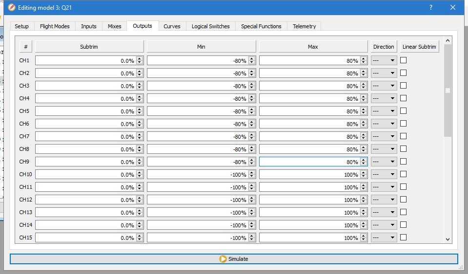
Another possible workaround is to alter the transmitter mixes so that ALL outputs range from a minimum of say -80% to maximum of 80%, so keeping the decoded signal within acceptable range for CF. Note that just one channel sending too high or too low a value may seriously disrupt decoding on the ‘copter.
The solution is that CF would benefit from a receiver calibration facility, and the one in Ardupilot is a good example.