The popular End Fed Half Wave is all things to all men, but this article compares an End Fed Half Wave, Inverted L, and Half Wave Dipole with some common parameters:
- frequency: 7.1MHz;
- flat top length: 20m;
- Height above ‘average’ ground (σ=0.005, εr=13): 10m;
- lossless balun / matching device.
Key differences:
- ground connection: Inverted L = 2Ω, End Fed Half Wave = 100Ω; and
- effective common mode choke used on the dipole.
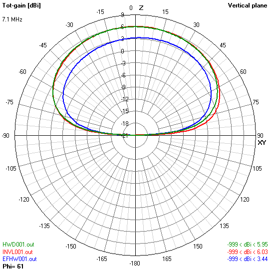
Above is the modelled gain for all three.
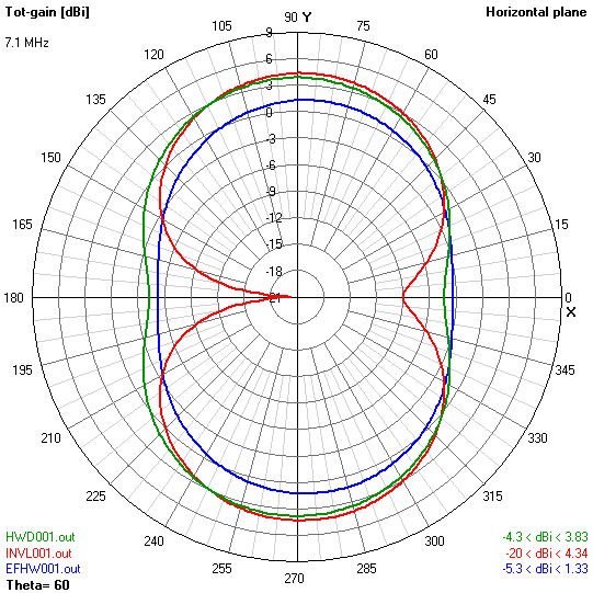
Above, the azimuth pattern at 30° elevation shows the effect of the current flowing in the vertical section.
Note that although the current magnitude distribution is similar on the End Fed Half Wave and Inverted L, the phase is different and that accounts for the different patterns.
Realist adjustments for feed line and matching device loss
The above plots assume lossless feed line and matching Actual losses are very dependent on implementation, but less me propose some realistic ranges for gain reduction due to those elements:
- End Fed Half Wave: 2-4dB;
- Inverted L: ~2dB; and
- Dipole: ~1dB.
Factoring those in, the EFHW becomes the stand-out loser.
The key losses that affect the EFHW in this model are:
- use of a makeshift / poor ground for common mode current… probably mostly out of ignorance /denial of the existence of that current;
- rather lossy impedance transformation network;
The Inverted L model performs better because it is assumed in the model that the implementor understands that significant current may flow to ground, and that a low R ground connection is critical to gain.
The well implemented Half Wave Dipole with effective current balun is mostly free of the ground current losses of the other two.