I saw a recent ‘maker’ video describing a small transmitting loop for 40m.
The loop used a 3m length of 19mm copper pipe formed into a circle, and at the gap where the ends almost meet, a tuning capacitance is synthesised using coaxial cable.
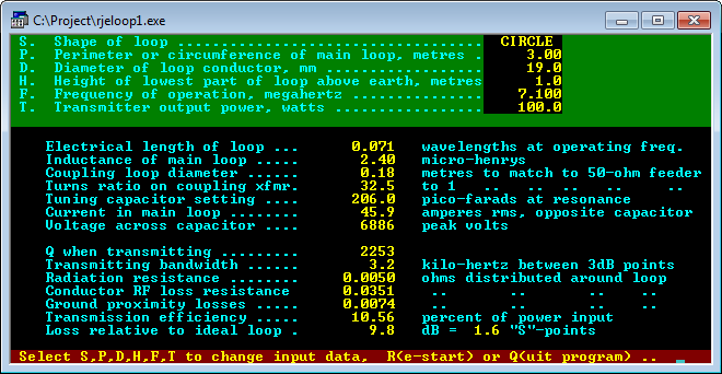
Above is a screen shot from Reg Edwards loop design program. It calculates the radiation resistance at 0.005Ω, loss resistance of the loop at 0.035Ω, capacitance to resonate it of 206pF (Xc=108Ω), and a bandwidth of 3.2kHz.
The video I mention used a variable capacitor fabricated from FR-4 PCB material at the end of 1.8m of RG213. Lets us assume the FR-4 capacitor to be 10pF and dissipation factor for FR-4 to be 0.18, the impedance of this capacitor will be 40-j2240Ω (note the large series resistance, FR-4 is a lossy dielectric).
Using TLLC, the input impedance of the coax section with the FR-4 capacitor is calculated as 0.3-j110Ω which reconciles really well with the predicted tuning reactance.
The total loop resistance now is 0.005Ω radiation resistance, 0.035Ω copper pipe resistance, and 0.30Ω equivalent series resistance for the tuning capacitance, making a total of 0.34Ω of which 0.005Ω is radiation resistance, a loop efficiency of 0.005/0.34=1.5% or a loss of 18dB (equivalent to 3 S points). There will be some further losses in the input coupling loop, but it should be possible to contain losses to under 20dB. The reality is that 90% of the input power is used to heat the synthesised tuning capacitance, it should get noticeably warm at 100W of carrier input to the antenna system.
The 10 fold increase in system loss should deliver half power bandwidth of about 10 times that given by the calculator, or about 32kHz.
Overall, the antenna system at 1m above ground could be expected to be around 25dB behind an efficient half wave dipole system at 10m height.
Clearly, the improvised tuning capacitance is the single lossiest element of the system, and loops that use a better tuning capacitance can be expected to perform much better (a quality vacuum cap should be about 8dB better).
An alternate design with 3mm copper conductor instead of 19mm tube, and four 0.5m sections of RG213 in parallel with the same poor PCB capacitor would be about the same efficiency, the increased loss of the 3mm being offset by the lower loss of the 4 shorter coax sections in parallel.
Summary
- Choosing low loss components for small transmitting loops is critical to efficiency.
- FR-4 makes lossy capacitors.
- Transmission line sections can make lossy reactors.
References
- Duffy, O. 2001. RF Transmission Line Loss Calculator (TLLC). VK1OD.net (offline).
- ———. 2012. PC high voltage RF capacitors. VK1OD.net (offline).
- Parker, P. 2014. 100 watt 7 MHz magnetic loop for units and apartments on Youtube. https://www.youtube.com/watch?v=Cv_RnLpZ9gw .