Under the heading “Wind your own balun “, the WIA’s “Your entry into amateur radio” 2nd ed (The Foundation licence manual) gives advice to newcomers on constructing a 4:1 Guanella balun, a current balun.
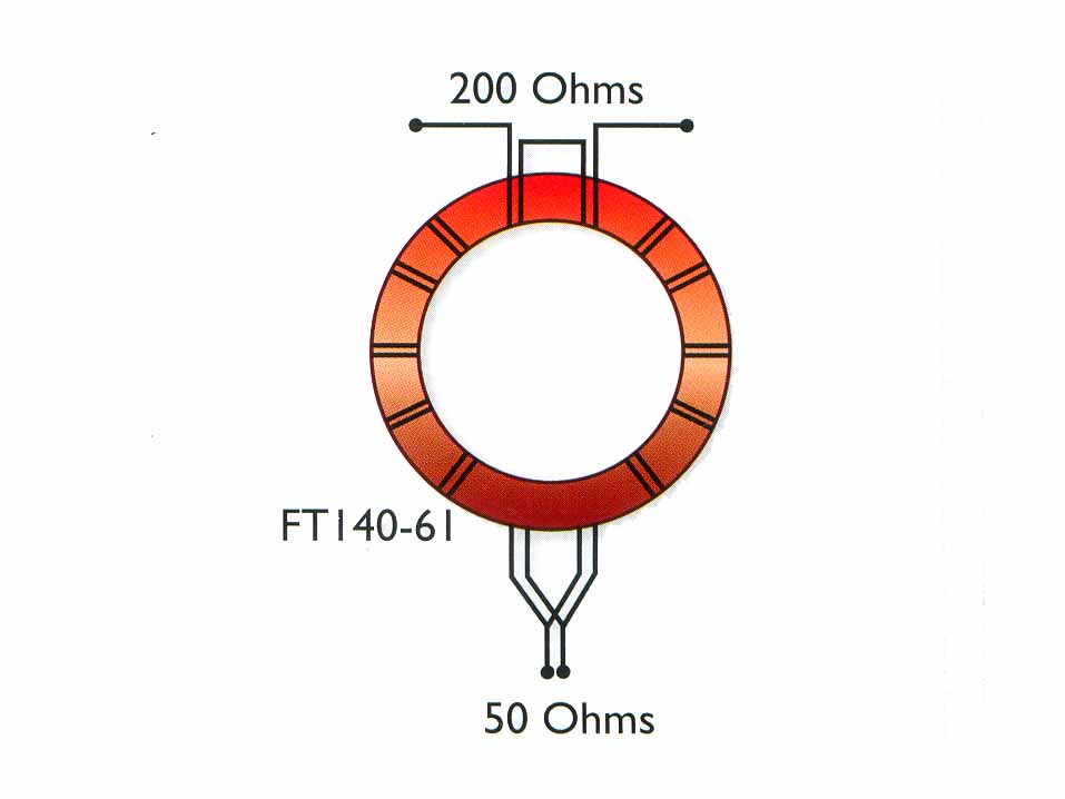
Above is a graphic from the article depicting the construction and connections. Though Guanella did describe a 4:1 current balun in his 1944 article, he did not show the winding pairs coupled by a magnetic core as shown above.
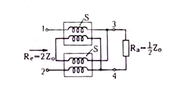
Above is Guanella’s circuit, and he does not show coupling between the two winding pairs.
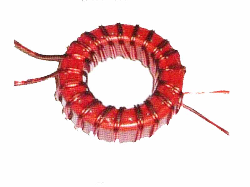
The above photograph is from the article, and it depicts a toroid with rounded corners and painted red. (Powdered iron cores are conductive and the rounded corners are to help prevent the core cutting through the wire insulation, the epoxy enamel is to help to insulate the conductive core from the wire.) These are a strong suggestion that this core is a #2 powdered iron core, yet the text further down recommends a FT140-61 ferrite core (which will usually be unpainted and have sharper corners.
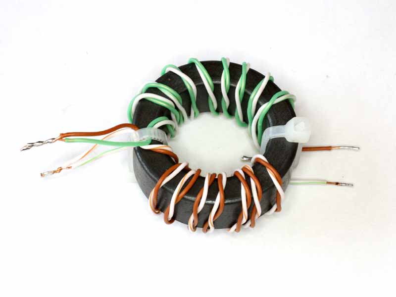
Above is a balun wound to the directions given in the article on a real FT140-61 (note the colour and corners).
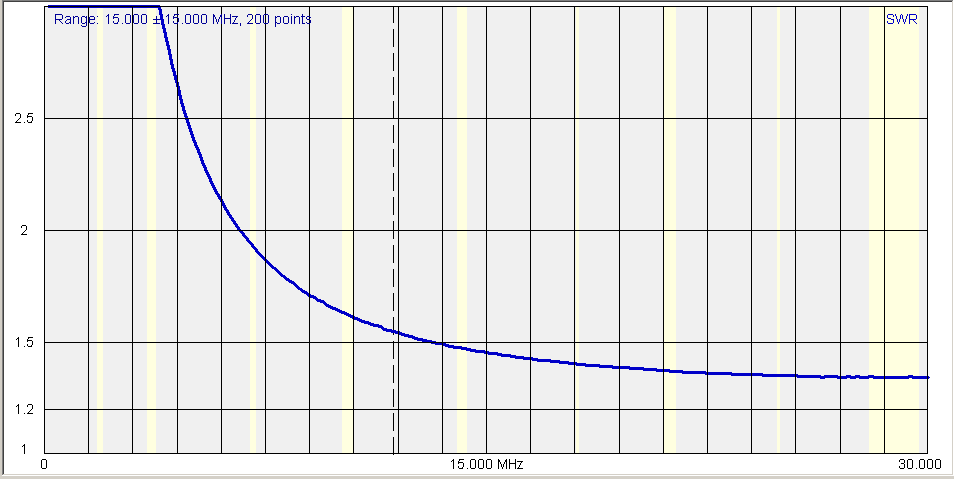
Above is a SWR measurement taken with a Rigexpert AA-600 of the balun as constructed with a 200Ω resistive load. For a good 4:1 current balun, we should expect that the SWR would be less than 1.1 over the desired operating range, 1.2 at worst.
On the 40m band, the SWR is 2.0, rising to over 3.0 in the 80m band, and the best is 1.4 in the 15m to 10m range.
Coupling the windings by placing them on the shared toroid reduces the balun’s ability to reduce common mode current, the reasoning is a bit technical for beginners and obvious to more advanced hams.
One of the most common applications for a 4:1 current balun is with an off centre fed dipole (OCF). OCF dipoles, being asymmetric, have propensity for high common mode feed line current and a current balun with very high choking impedance can help to mitigate this inherent problems with OCF dipole.
This is simply not a good balun design, its transfomation ratio departs significantly from the nominal ratio and its ability to reduce common mode current is compromised. No doubt there are many hams using this balun design, people who wouldn’t know any better and would be sure it “works real good”. This is ham radio!
Winding your own balun is a great project… but you need to start with good information, and current balun designs that do not include relevant measurements (including common mode impedance) are unknowns.
It is true that this design is straight out of (Sevick 2001), (Fig 9-9 right). Sevick states the design as suitable for “floating balanced loads” which implies a load with no current flowing to ground or a third terminal. He refers also to “isolated loads” in some other designs. This is patent nonsense as there is no need for a balun for such a load as with only two terminals the current into one leg MUST exactly match the current out of the other leg.
More at WIA 4:1 current balun – further explanation and WIA 4:1 current balun – further measurements.
References
- Duffy, O. 2008. A review of the Guanella 4:1 balun on a shared magnetic circuit. VK1OD.net.
- Sevick, J. 2001. Transmission line transformers 4th Ed. Noble Publishing Co. p9-17.