K4PP described his Small Transmitting Loop (STL), including details of its construction and measured VSWR response.
The loop is a 1m diameter circle of 12.7mm dia copper tube with a high Q vacuum cap for tuning.
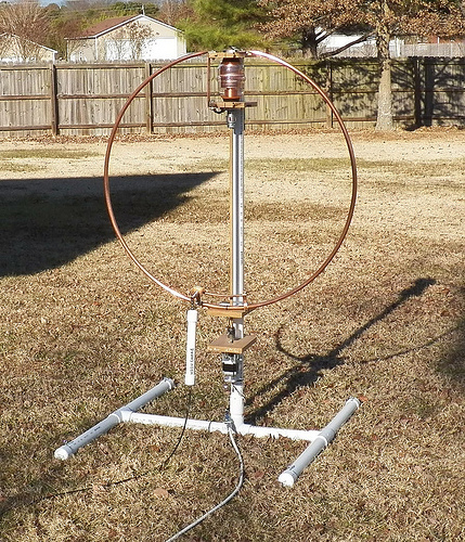
Using a quality capacitor and copper tube, this loop should be as efficient as they come for its size and location.
Above is a pic of the loop, and it would appear that the centre is about 1m above ground.
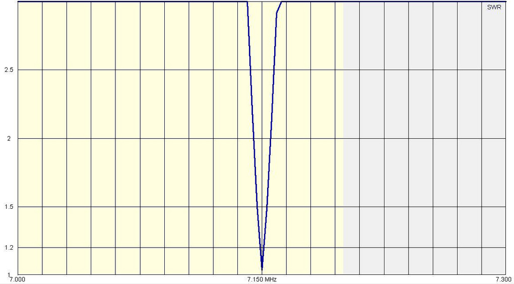
Above is K4PP’s measured 40m VSWR. Bandwidth at VSWR is scaled from the plot as 15kHz.
Analysis
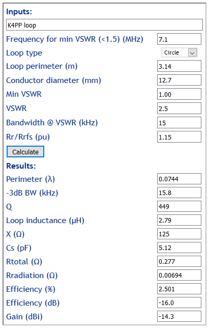
Above is calculation using Calculate small transmitting loop gain from bandwidth measurement of some key loop performance figures from K4PP’s information. Impedances are expressed in terms of the main loop. Rr/Rfs is estimated using the graph in Small transmitting loop – ground loss relationship to radiation resistance.
We might expect the 0.277 Rin to be made up of:
- 0.007Ω Rrad;
- ~0.030Ω Rgnd;
- 0.065Ω Rloop;
- 0.075Ω unallocated (Rcap, connection resistance, matching system, coupling to nearby structures, errors in other estimates), 75mΩ does seem high to allocate entirely to the cap.
Efficiency
Though there is a significant unallocated component of Rin, the magnitude of Rin is calculated with fairly low uncertainty from the loop dimensions and measured VSWR curve.
The Rr component of Rin has uncertainty, and extensive modelling with a range of ground scenarios gives good reason to think that the uncertainty for most commonly encountered ground types is ±3dB, which dominates the efficiency calculation and would make the confidence limits of efficiency -19 to -13dB, or 1.3% to 5.0%.
References / links
Calculate small transmitting loop gain from bandwidth measurement