Small Transmitting Loops behave fairly much like an ideal inductance in series with some small resistance. They do however exhibit a self resonance at a frequency where the perimeter is approximately a half wavelength. This can be expected to slightly alter the Xl vs frequency characteristic below the self resonant frequency (SRF), more so as the SRF is approached.
This departure can be compensated for to some extent by addition of a small equivalent shunt capacitance.
Most calculators for small loops seem to use a formula given by (Hart 1986) that Cs=0.82*PerimeterInFeet. This does not reconcile well with NEC-4.2 models of STL.
(Straw 2007) gives a different formula for circular loops, derived from Medhurst’s work with solenoids, but again the values do not reconcile well with NEC-4.2 models of STL.
NEC-4.2 model of STL
A series of models were run of a 1m diameter lossless loop with a range of conductor diameters and the SRF tabulated. A curve fit was made of ln(LoopDiameter/ConductorDiameter) against observed SRF adjustment factor (being SRF relative to c0/(2*length)).
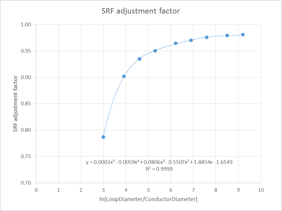 Above is a plot of the results, and a polynomial curve fit to facilitate estimation of the SRF of a loop of given LoopDiameter/ConductorDiameter.
Further work needs to be done to determine if there is a constant equivalent self capacitance that explains the impedance vs frequency characteristic of a STL (as commonly assumed).
References
- Hart, Ted (W5QJR). 1986. Small, high efficiency loop antennas In QST June 1986.
- Straw, Dean ed. 2007. The ARRL Antenna Book. 21st ed. Newington: ARRL. Ch5.