A reader of Why the preference for Guanella 1:1 current baluns for HF wire antennas asked if a similar model can be built for a Ruthroff 4:1 balun.
Hams tend to insist that the Ruthroff 4:1 balun cannot be represented by transmission line elements, but they are quite wrong.
I was regularly told that a model I came to (Duffy 2007) was not valid and it was some years after I had developed the model that I obtained a copy of Ruthroff’s paper which indeed showed such a model. My work was not novel, I had independently come to the model which Ruthroff had shown 40 years before.
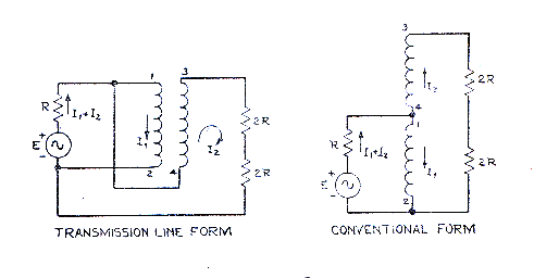 Above, Ruthroff’s diagram of the basic 4:1 balun (Ruthroff 1959).
The device in the left hand size is similar to that of the Guanella 1:1 balun with different end connections.
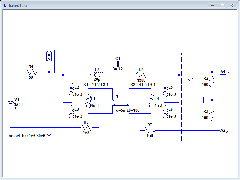
Above is the structure used for the Guanella 1:1 balun in the article Why the preference for Guanella 1:1 current baluns for HF wire antennas rewired for the Ruthroff 4:1 configuration, though the choke values are changed to suit the application. The components inside the dashed box represent the tranmission line wound around a ferrite core.
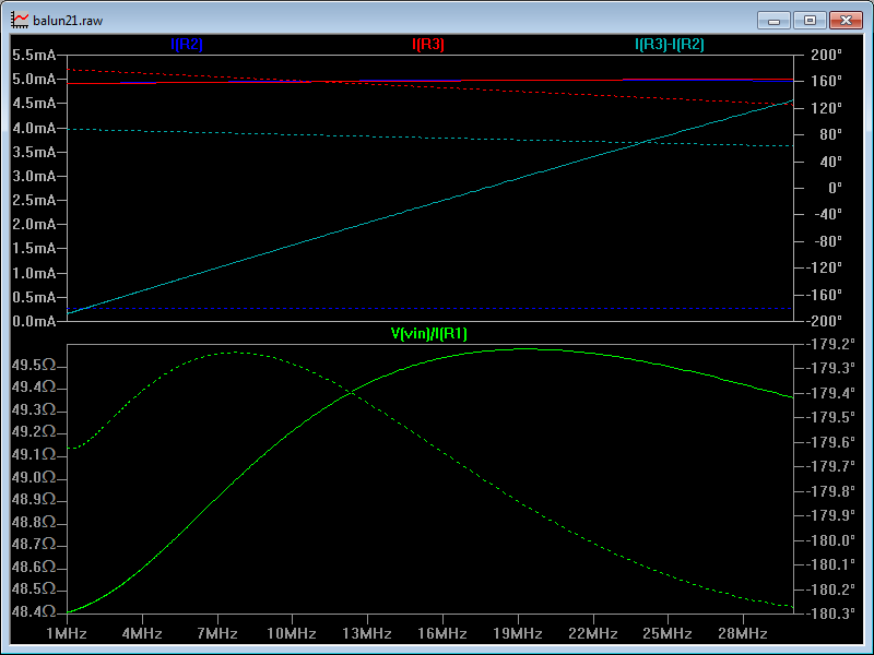
Above is the model response. Note that common mode current (I(R3)-I(R2)) grows with frequency even though the magnitude of I(R3) and I(R2) don’t change much, this is a result of the phase change through the transmission line. This is the main cause of high frequency roll off of this type of balun, and whilst it is predicted by the TL equivalent circuit, it is not predicted by Ruthroff’s “conventional form” circuit as shown.
The low frequency roll off is also predicted, and it is due to the impedance of the common mode path, larger L and R will lower the lower frequency limit. Note though that increasing L by adding turns increases the TL length which lowers the upper frequency limit.
Note that the representation of the common mode inductor is not a good way to represent a ferrite cored inductor due to the variation in µ’ and µ” with frequency, (Duffy 2006).
Common mode impedance
The common mode impedance for a good voltage balun should be very low.

Above is the common mode impedance for the modelled configuration but with the load split assymetrically 150 and 50Ω.
Voltage baluns do little to minimise common mode current on assymetric loads.
References / links
- Duffy, O. 2006. A method for estimating the impedance of a ferrite cored toroidal inductor at RF. VK1OD.net (offline).
- ———. 2007. A model of a practical Ruthroff 1:4 balun. VK1OD.net (offline).
- ———. 2012. Calculate ferrite cored inductor. https://owenduffy.net/calc/toroid.htm.
- Ruthroff C. 1959. Some broad band transformers. Proceedings of the IRE.