I am often asked why I recommend a Guanella 1:1 balun with high choking impedance for most HF wire antennas over voltage baluns and 4:1 current baluns. This article explores the topic using SPICE models for a voltage balun, 1:1 current balun, and 4:1 current balun.
Purpose of baluns in antenna systems
The balun’s principal purpose is to prevent participation of the transmission line radiating on tx or picking energy up on rx, to commit the transmission line to the sole purpose of conveyance of energy from the transmitter to the antenna feed point.
Not all antenna systems are intended to work that way, but for those that are, the balun function is very important.
Voltage balun
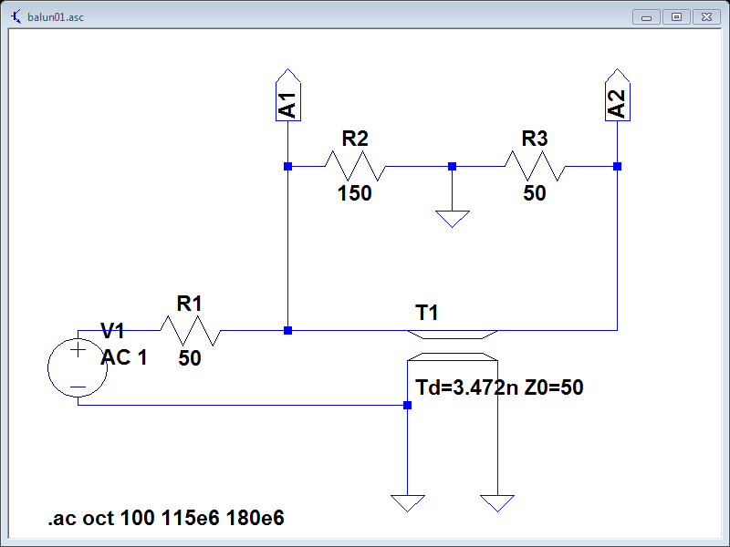
Above is a SPICE model of a voltage balun for VHF that uses an ideal half wavelength of coax. The load is intentionally asymmetric to illustrate the weakness of voltage baluns on this type of load.

Above is a plot of the current in each load resistance. It can be seen that at the design frequency, current in R2 is 2.9∠180mA , current in R3 is 8.6∠-180mA, and common mode current I(R3)-I(R2) is 5.7mA. This balun is extremely poor at forcing equal but opposite currents in the load conductors.
That is not surprising, good voltage baluns drive equal but opposite voltages on the output terminals, and the currents are only balanced for symmetric loads.
Guanella 1:1 current balun
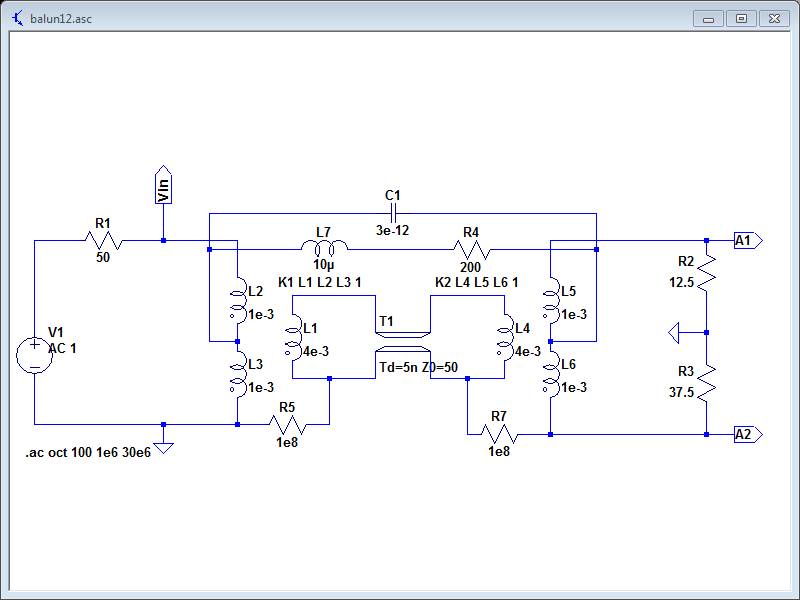
Above is a SPICE model of a Guanella 1:1 current balun for HF that uses an electrically short length of transmission line wound around a ferrite core. The model is based on (Duffy 2008). The load is intentionally asymmetric to illustrate the strength of current baluns on this type of load.
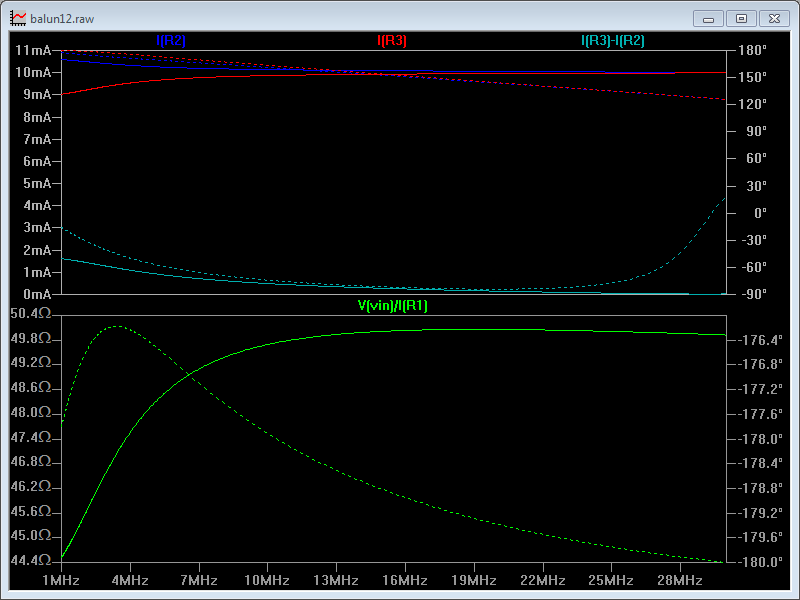
Above is a plot of the current in each load resistance. It can be seen that at mid range, current in R2 is 10.1∠152mA , current in R3 is 9.9∠-153mA, and common mode current I(R3)-I(R2) is 0.26mA. The two load resistance currents are almost the same, and common mode current is very small. This balun is extremely good at forcing equal but opposite currents in the load conductors.
That is not surprising, good current baluns drive equal but opposite currents at the output terminals.

Above, a plot of common mode impedance which is 683∠62 at 7MHz. (This balun is not a very high Zcm balun.)
Guanella 4:1 current balun
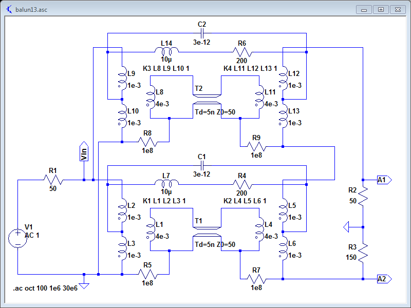
Above is a SPICE model of a Guanella 4:1 current balun for HF that uses two component baluns of the type used in the previous case, connected to provide a 4:1 impedance transformation. The load is intentionally asymmetric to illustrate the strength of current baluns on this type of load.
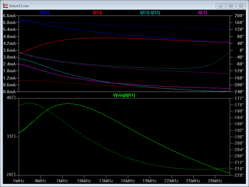
Above is a plot of the current in each load resistance. It can be seen that at mid range, current in R2 is 4.9∠144mA , current in R3 is 4.6∠-209mA, and common mode current I(R3)-I(R2) is 0.64mA. The two load resistance currents are close, and common mode current is small. This balun is good at forcing equal but opposite currents in the load conductors, , but not as good as the Guanella 1:1 balun.
Also notable in this case is that the impedance transformation departs much more from ideal, and the lower frequency roll off starts at a higher frequency.
The Guanella 4:1 balun does not simply behave similarly to the component 1:1 baluns that it is made from.
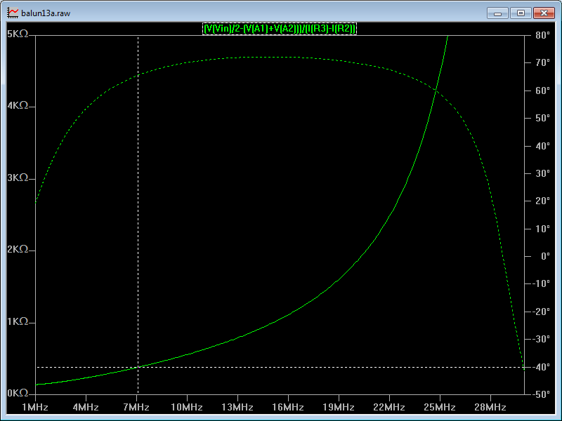
Above, a plot of common mode impedance which is 382∠65 at 7MHz, just over half that of the component baluns. (This balun is not a very high Zcm balun.)
Typically, a Guanella 4:1 balun delivers a quarter of the common mode impedance that would be achieved if the two component baluns were used in cascade for a 1:1 transformation.
If you MUST have 4:1 transformation, look at the hybrid Guanella 1:1 / Ruthroff 4:1 cascade, it is probably a better solution.
References / links
- Duffy, O. 2008. A model of a practical Guanella 1:1 balun. https://owenduffy.net/files/GuanellaBalun01.pdf.