This article documents a line-up procedure for the MFJ-1270B TNC. This is an advanced procedure, you should not tackle it without appropriate knowledge and experience.
Equipment required;
- Scope to view audio square wave.
- Frequency meter for audio tones (could be a DSO if it measures frequency accurately).
- Computer with terminal program configured to talk to the monitor program.
The alignment procedure adjusts both 300Bd mode and 1200Bd mode, both should be done even if the intended use is at only one of the speeds. The sequence is critical, follow the steps in order, moving on only after successful completion of each step.
Modem calibration
- Turn off the power
- Remove the radio interface cable
- Install an EPROM with a monitor with the CAL command if not already installed.
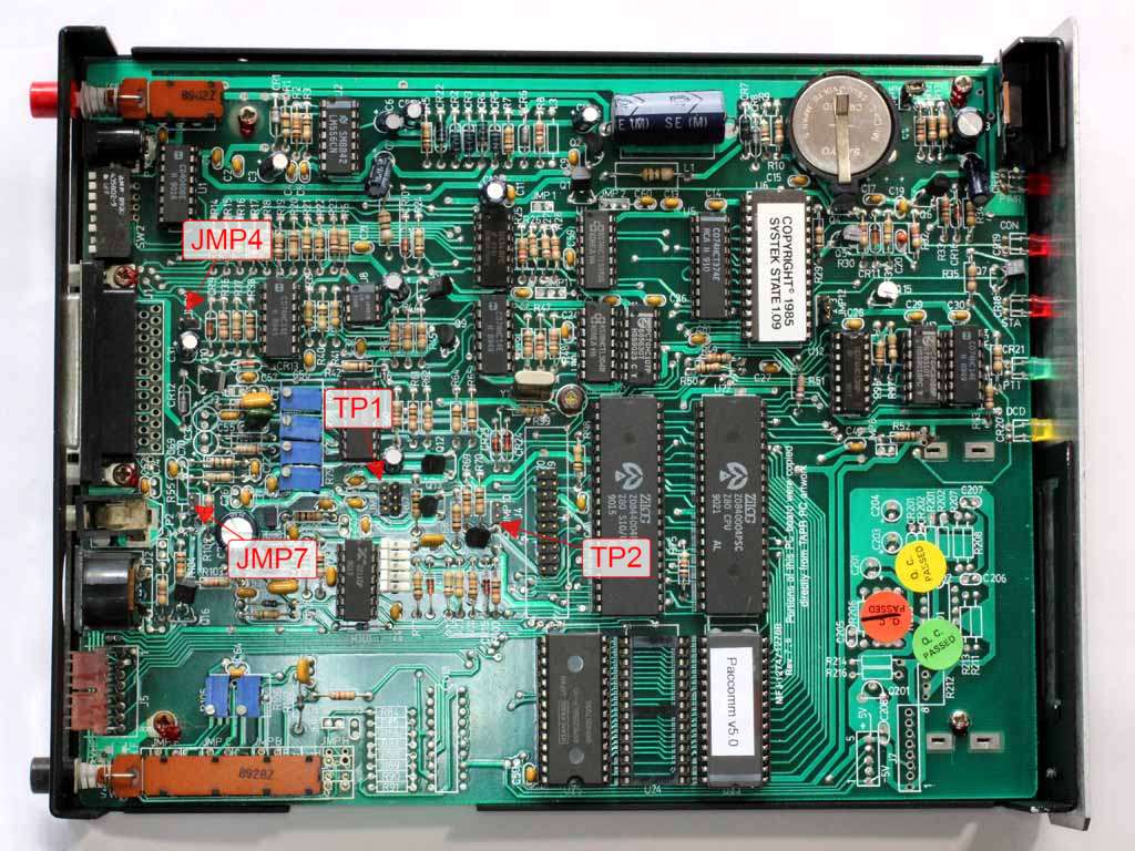
- Install links at JMP4 and JMP7 (see pic above).
- Write down rear speed switch settings.
- Set the rear switches to 5, 6 ON, others OFF.
- VHF/HF switch out (VHF).
- Connect frequency meter to JMP9 pin designated TP1 in the pic above.
- Power on.
- Enter CAL command, then K to KEY up (PTT LED should light).
- Hit space bar to select the nominal 2200Hz tone (Spacebar toggles between high and low tone).
- Adjust R77 for 2200Hz.
- Hit space bar to select the nominal 1200Hz tone.
- Adjust R78 for 1200Hz.
- Push VHF/HF switch in.
- Hit space bar to select the nominal 1800Hz tone.
- Adjust R105 for 1800Hz.
- Hit space bar to select the nominal 1600Hz tone.
- Adjust R106 for 1600Hz.
- Enter D to send isochronous signal (DUAL tones alternating).
- Connect scope to J10 pin designated TP2 in the pic above.
- Adjust R79 for symmetric square wave.
- Power off.
- Remove JMP4 and JMP7, restore speed switches.
- Connect to radio, power on and test.
The astute will note that step 22 adjusts the VCO centre frequency in 300Bd mode. That adjustment is more critical than if the TNC was in 1200Bd mode, so since there is only one adjustment, it is best performed in 300Bd mode even if you do not intend using that mode.
An earth can be found at the anode end of CR12 near the DB25 connector.
Clock oscillator calibration
The clock oscillator is 4.915200MHz, 512 times 9600. (Note there is contrary advice on the ‘net that the oscillator is 4.915205MHz, but it is wrong!)
The clock can be sampled from pin 1 of JMP2, and C47 (next to the crystal) adjusted for 4.915200MHz.
The main advantage of accurate clock is that it makes the internal clock more accurate if used (eg in UIDIGI).