A lot of radios are made today to use an electret microphone which has a higher output than common dynamic capsules and may require a preamp to comfortably obtain sufficient audio.
This article describes a microphone + preamp intended as a drop in replacement for an electret capsule.
An electret capsule contains an integral FET preamplifier, and the common two terminal version of the capsule depends on an external load resistor (commonly around 4.7kΩ and source of supply current (commonly from 6-12V via the load resistor.
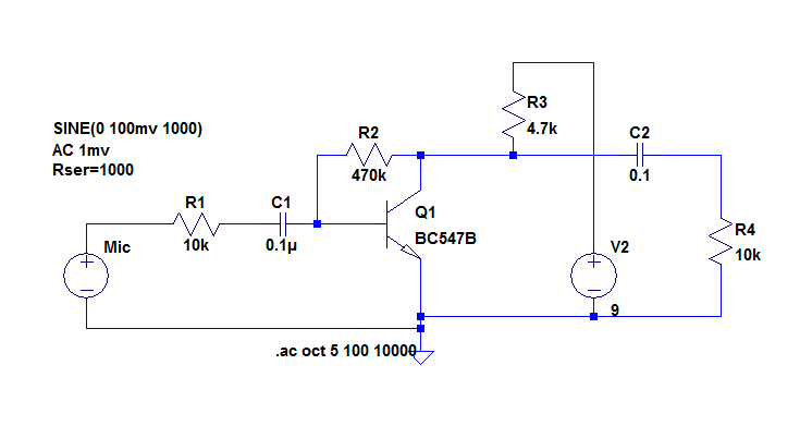 Above is the preamp schematic from an LTSpice model. A common emitter amplifier operating in this circuit has re of about 20Ω, and so voltage gain from collector to base is very high at 3000/20=150 (assuming total collector load of 3kΩ).
V2, R3, C2 and R4 are for modelling purposes, they will usually be supplied by the existing transceiver circuit for the electret input.
R1 has been added to increase the input resistance a little, and reduce overall gain to about 28dB in this configuration. R1 in concert with R2 stabilise / control overall voltage gain. Low input impedance may alter the tonal response of the microphone, this circuit results in around 12kΩ input resistance.
capacitors are chosen for a lower rolloff well below 300Hz.
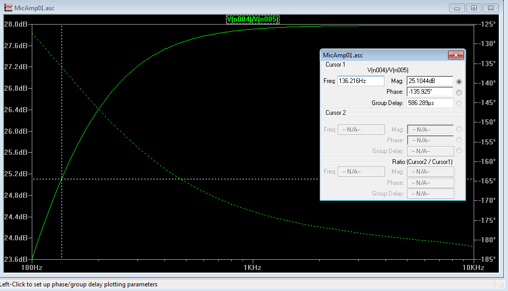 Above is the model result for frequency response, lower break point is 136Hz. You don’t want this too low, but you want it well below 300Hz.
If the gain is too high for the application, some resistance can be connected from the junction of R1 and C1 to the ground terminal, and in that case C1 should be doubled in size.
The ground terminal is of course the MIC GND in radios that use a separate MIC ground, the same ground as used by the electret.
In transmitters, RF ingress is a problem, and depending on your own configuration, some ferrite beads and small bypass capacitors may be necessary to prevent RF feedback.
The preamp will saturate at something around 1Vpk so it has more than adequate headroom for the application.
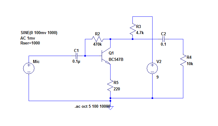
Above, an alternative circuit for reducing gain by inclusion of R5, chosen for the required gain. There is negative feedback via R2, and R5 introduces negative feedback that stabilises / controls overall voltage gain.