Standards
AS/NZS 2272.2 sets out in Appendix E a method for calculation of near field strength of antennas, citing ANSI C95.3—1973 as authority.
This article comments on application to antennas other than those with a circular aperture.
AS/NZS 2272.2 states:
The near-field gain is always less than the far-field gain and is determined by subtracting the appropriate gain reduction for both horizontal and vertical planes from the far-field gain. Therefore, by use of this gain reduction in the far-field equation, the near field can be calculated.
The following figure is given for solution of antennas with estimated uniform illumination.
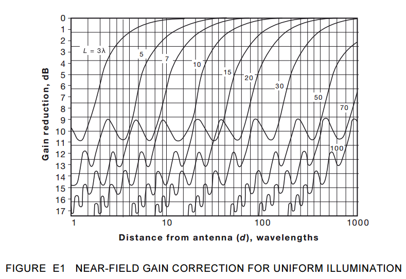
In view of the statement quoted above and FIgure E1, readers could be forgiven for thinking that curves for antennas of dimension less than 3λ will fall entirely in the upper left corner of Figure E1, and that to assume no gain reduction would be a conservative position.
NEC-4 model of a short dipole
A 1m vertical thin dipole was modelled in free space at 14MHz radiating 100W, and the near H field reported.
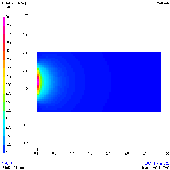
Above is a partial map of the H field, the dipole centre is located at (0,0). It is only at the very right hand edge of this chart at 3.5m distance that the time averaged H field falls below the ARPANSA requirement of 0.073A/m. The on-axis exclusion zone is therefore 3.5m.
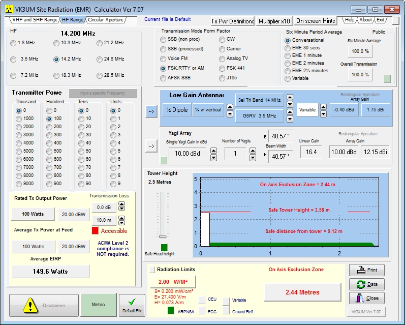
Above, the popular tool EMRCalc which claims to follow AS2272.2 (an expired predecessor to AS/NZS 2272.2) calculates the on-axis exclusion zone as 2.44m.
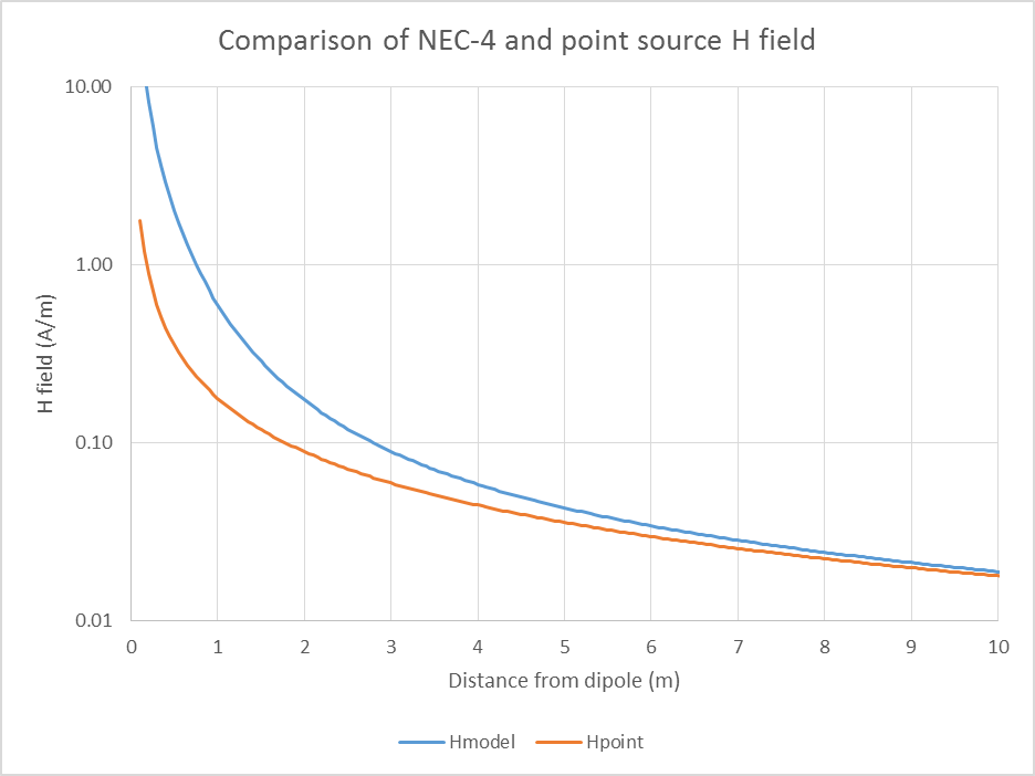
Above is a plot of the H field along a line normal to the centre of the dipole as calculated by the NEC-4 model. Also plotted is the H field calculated by a point source model with same EIRP, and at a distance of 1m in this case, it underestimates H field by around 10dB. The H field calculated by NEC is greater than the point source H field, so contrary to the statement quoted from AS/NZS earlier,the near field gain is higher than the far field gain.
Conclusions
- NEC modelling of a short dipole suggests that near field gain may be greater than far field gain.
- AS/NZS 2272.2 may be wrong in the general assertion that it makes that
the near-field gain is always less than the far-field gain.
li> - EMR modelling tools that depend on as assumption that
the near-field gain is always less than the far-field gain
may give wrong answers for a short dipole, and for the same reasons, other physically small antennas. - FCC OET65 may depend on the same source (ANSI C95.3—1973) and have the same issues.
- This may have implications for physically small transmitting antennas (eg so called magnetic loops), especially when employed indoors.
References
- ARPANSA. 2002. ARPANSA Radiation Protection Standard (RPS3 2002) – Maximum exposure levels to radiofrequency fields – 3kHz to 300GHz (assuming plane wave conditions).
- AS/NZS 2272.2. 2011. Radiofrequency fields
Part 2: Principles and methods of measurement and computation—3 kHz to 300 GHz.