Martin Ehrenfried (G8JNJ) conducted some interesting experiments on a small transmitting loop.
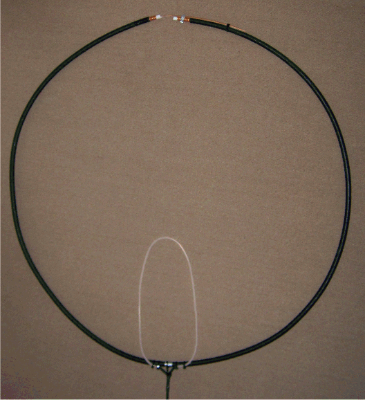
The loop above is 3.45m perimeter of LDF4-50A Heliax, and uses the full length of the Heliax as a stub for tuning the loop to 5MHz.
The antenna is similar in concept to my 4MHz RG213 loop discussed at A QRP small transmitting loop evaluation though the LDF4-50 should have lower internal losses.
Martin took a thermograph of the loop after a period at 200W input.

The thermograph above is oriented as per the photograph above, and it is notable that the region near the top and to the left of the top are higher temperature, tapering down as one travels anticlockwise around the tloop.
Why does this happen?
Some key details…
- The loop perimeter is about 0.06λ, so exterior current is almost uniform around the loop.
- The LDF4-50 inner conductor perimeter is about one third of the outer conductor, so at the input end of the loop, for every milliwatt lost due to current in a segment of the outside surface, there is another milliwatt due to current on the inside of the shield, and three milliwats due to current on the outside surface of the centre conductor, total of five times that of the outer surface alone. Obviously the inside current tapers, and I^2R diminishes quickly.
- 3.45m of LDF4-50A at 5MHz is an electrical length of about 23°, and current flowing on the inside of the coax (the stub current) will taper almost linearly from full loop current at the input end to zero and the o/c end, and conductor loss is i^2R.
- The internal (or stub) voltage rises almost linearly by about 9% from input end to the o/c end, so internal dielectric loss (E^2G) around the loop is almost uniform.
The temperature gradient on the thermograph shows that stub I^2 losses in the first quarter of the stub are relatively large. Outer surface conductor loss and internal dielectric loss appear relatively low as much of the loop is near ambient temperature.
The thermograph is a stunning illustration of how bad coax can be as a ‘capacitor’… yet it features in lot of implementations.
Well done Martin!
References
- Duffy, O. 2014. A QRP small transmitting loop evaluation.
- Ehrenfried, Martin. 2014, Quick build 5MHz loop. http://g8jnj.webs.com/currentprojects.htm (accessed 17/06/2014).