This article discusses the concept of circuit Q, its application for antennas and assessment of antenna Q.
Q factor
(Terman 1955) gives a general definition of Q that is widely accepted:
circuit Q is 2π(energy stored in the circuit)/(energy dissipated in circuit in one cycle) .
Q is easily assessed for a single reactor:
- inductor: energy stored is L*Ipk^2/2 and energy lost per cycle is I^2R/2f so Q=2πfL/R=Xl/Rs;
- capacitor: energy stored is C*Vpk^2/2 and energy lost per cycle is V^2/(2fRp) so Q= 2πfCRp=Rp/Xc.
A RLC series resonant circuit is nearly as easy as at the instance when the inductor current is maximum, capacitor voltage is zero and hence the energy stored is as per the simple inductor case and Q=Xl/Rs.
Likewise for a parallel RLC resonant circuit, at the instant of maximum capacitor voltage, inductor current is zero and hence the energy stored is as per the simple capacitor case and Q=Rp/Xc.
Response of series RLC circuit
The current in a series RLC circuit excited by a constant voltage is maximum at the resonant frequency Fr (that where Xl=Xc) and falls off above and below that frequency.
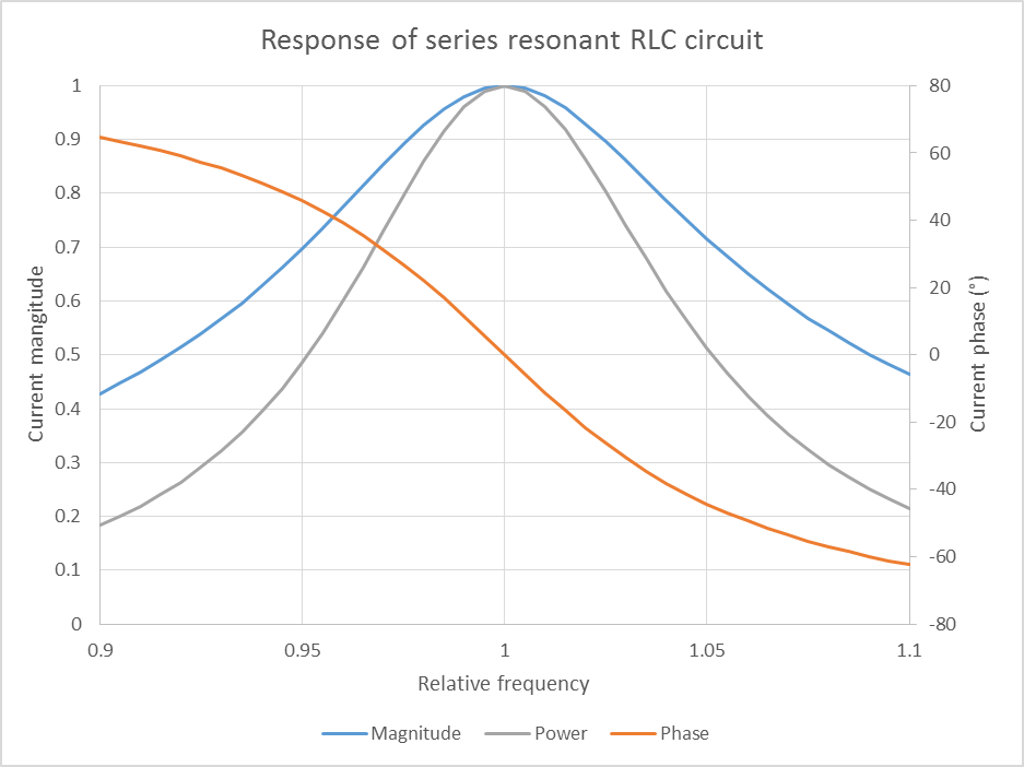 Above is a chart of relative current and power developed in a series RLC circuit with constant voltage drive. Xl=Xc=10 at Fr=1, and R=1. By the definition above, this circuit has a Q of 10.
The current is maximum at resonance, and falls off at higher and lower frequencies where the net reactance increases. Since P=I^2R, power is maximum where the magnitude of current is maximum and falls of as the square of current magnitude. It can be seen that the bandwidth between half power points is 0.1 of the resonant frequency, this is known as the half power bandwidth BW, and BW=Fr/Q, or rearranging Q=Fr/BW.
At the half power points, current has fallen to 70.7% of maximum because |X|=R, and so |Z| is 141% of that at resonance (R).
Also shown is the phase angle of current, note that it is +/-45° at the half power points.
So, there are several indicators of the half power points:
- current falls to 70.7* of maximum (with constant source voltage);
- R=|X|; and
- |phase|=45°,
any of these can be used to find the upper and lower half power points.
Measuring Q of a series RLC circuit
To make measurements of a circuit to create the chart above, you might connect a signal generator to the series circuit and insert an ammeter to measure the current. You would also monitor the output voltage of the generator and adjust it to give a constant voltage at all frequencies measured.
If you made these measurements with a 50Ω Standard Signal Generator (ie a source of a constant open circuit voltage and series resistance of 50Ω), the voltage impressed across the RLC circuit will vary with current and you cannot simply use the current response of the network to directly measure the half power bandwidth, you must factor in the changing voltage.
If you have some form of impedance meter, antenna analyser that can measure |X| and R, or a one or two port VNA you can find the resonant frequency (X=0) and half power points by finding where R=|X| or |phase|=45°. Dividing the resonant frequency by the difference between the half power points, you have the circuit Q.
Do not be tempted to interpret S21 -3dB points as half power points for the antenna… think about it.
Resonant antennas
Some antennas, but not all, are resonant, and of those, some exhibit a simple series resonance near the desired operating frequency. Examples include a half wave dipole, a quarter wave monopole, shortened loaded monopoles, small transmitting loops.
A significant difference between such antennas and the simple RLC circuit discussed above is that R is not necessarily constant, it may vary with frequency. However, for many antennas of this type, R changes very slowly compared to X and the results are reasonably well approximated by considering R to be constant.
Example: small transmitting loop
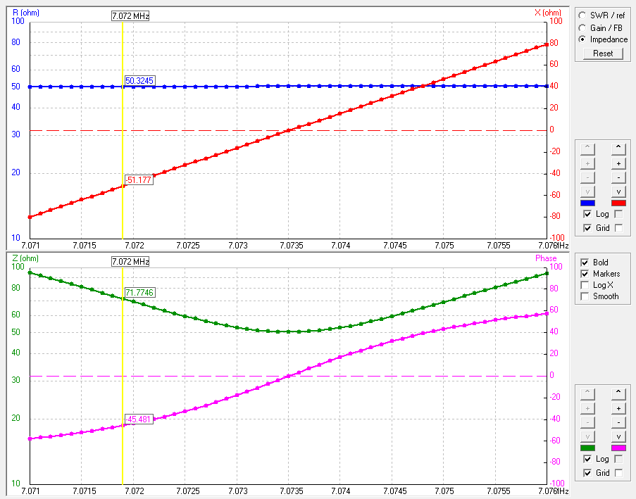
Above are NEC-4 plots of impedance of a small octagonal transmitting loop of 3.3m perimeter driven at 7MHz through a broadband matching transformer.
In this case, R is almost constant and X changes almost linearly with frequency. The cursor is located where R is approximately equal to X, the lower half power point, which on the lower plot has a impedance phase angle of approximately 45° (note that phase of impedance is negative of phase of current as shown in the first diagram).
The half power bandwidth is approximately 3.1kHz, so Q=7075/3.1=2282.
An alternative method of evaluation of Q from the R,X plot where R is approximately constant is that Q=fr/(2*R)*dX/df. In this case dX/df is about 32Ω/kHz giving Q=7074.8/(2*50.3)*32=2250.
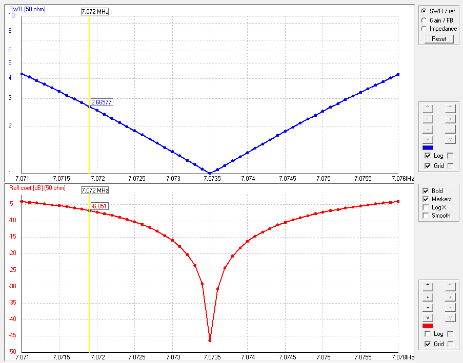
Above is a plot of VSWR and return loss for the same antenna. The lower half power point is indicated by VSWR=2.62, or ReturnLoss=7.0dB
So where an antenna of this type is perfectly matched at one frequency, the half power bandwidth of the antenna, and then its Q can be determined using an accurate VSWR meter or suitable antenna analyser. A QRP small transmitting loop evaluation does just that using an antenna analyser VSWR sweep.
Example: short loaded monopole
A helically loaded mobile whip for 40m was measured using a Rigexpert AA-600.
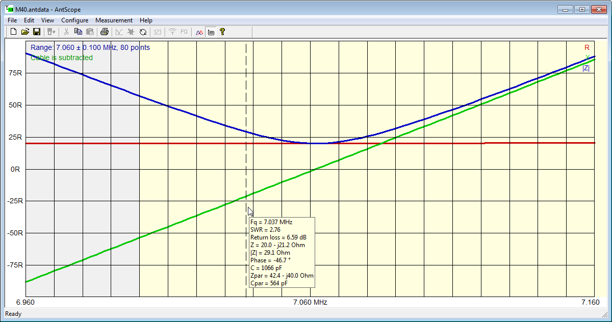
Above is a plot of feed point impedance, and it can be seen that it is not matched to 50Ω coax as R at resonance is about 20Ω. This chart has been calculated for Zo=20Ω (so VSWR(20) is displayed).
Note though that R is almost constant and X changes almost linearly near resonance. The cursor is located near the lower half power point (X=R, VSWR=2.62).
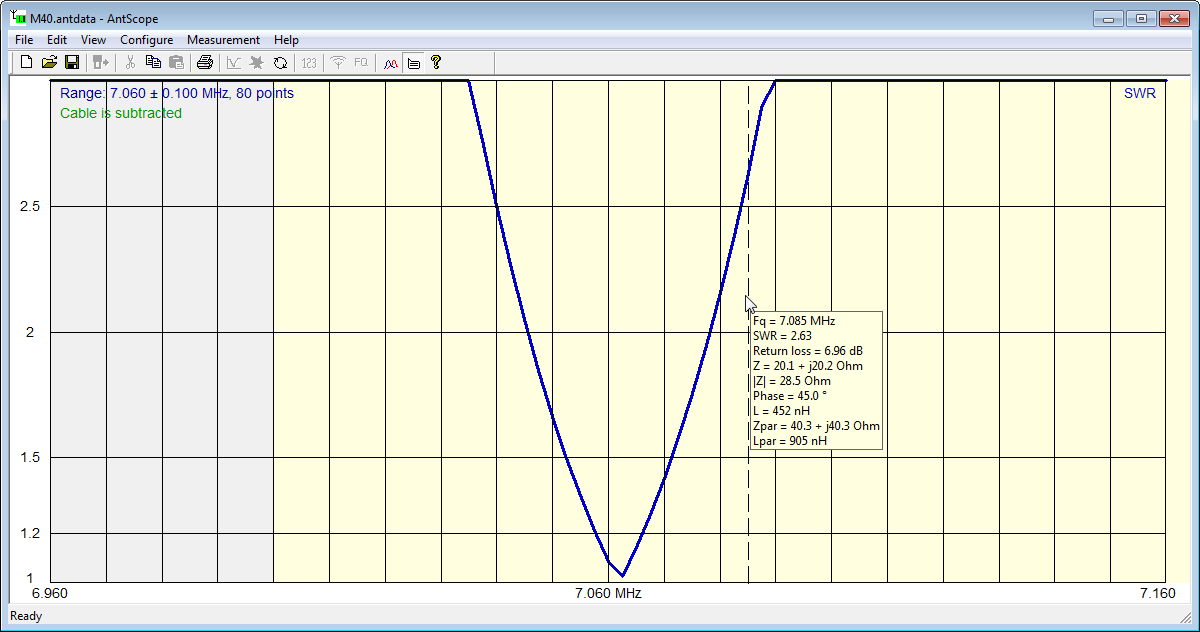
Above is a plot of VSWR(20) for the same antenna. The cursor is located close to the upper half power point, and the half power bandwidth is approximately 47kHz, so Q=7063/47=150, much lower than the small loop, but still much higher that a typical half wave dipole at around 10.
More complex circuits
Q can be determined for more complex circuits though the calculations may become quite complicated. The analysis starts with the general meaning of Q given above (circuit Q is 2π(energy stored in the circuit)/(energy dissipated in circuit in one cycle) then carefully calculating the total energy stored at some instant, and the energy dissipated in one cycle.
Conclusions
- Q factor is a well established concept, and well defined;
- Q of simple series RLC and parallel RLC circuits are easily calculated and easily measured.
- Antenna Q is a property of the antenna alone (don’t include source or instrument impedance);
- Q of a matched antenna can be evaluated by several methods, some using quite basic equipment.
References
- Terman, Frederick. 1955. Electronic and Radio Engineering – 4th ed. New York: McGraw-Hill.