A recent purchase of an inexpensive ($6) speaker polarity tester prompted a need for a stand alone driver for speakers.
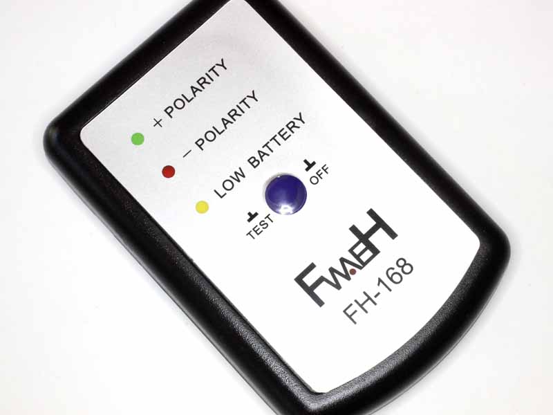
Above, the tester has a microphone that senses the polarity of the pressure wave and indicates with one of two LEDs.
The tester comes with a CD containing a file that can be used to provide the test signal on a complete system with CD player, but there is a need for a stand alone driver for testing bare speakers or speaker units.
An ESC based solution
A framework for a possible solution is an Electronic Speed Controller used widely with brushless sensorless DC motors on UAVs and available at very low cost.
The BS12A ESC used has some useful elements on board:
- Atmega8 microcontroller;
- three n-Fet half H bridges connected to the MCU, only two are needed; and
- 5V regulator for the microcontroller.
The one used came from spare stock and cost about $7 a few years ago.
Code was developed in the Arduino workbench (the hardware is Arduino compatible).
 Above, the BS12A with superfluous connections removed, reprogrammed and wrapped in clear heatshrink. It needs 7-18VDC and can switch up to 12A. The generator was successfully tested on a 9.6V NiMh pack, I would not try to use it on a common 6LR61 9V battery. It generates 250µs pulses 1s apart, in a repeating sequence of three positive ones followed by one negative one.
The accepted convention is at +ve voltage applied to the speaker’s + terminal should create a positive pressure transient in front of the speaker cone.
A compliant speaker when connected + to + to the tester will result in three flashes of the + (green) LED, then one of the – (red) LED, and so on repeating.
Here are the source code elements, bs_nfet.h and stg.ino.
//==================================================================================
//bs_nfet
//Port D
#define rcp_in 2
#define rcp_in_port PIND
#define AnFET 5
#define ApFET 4
#define INIT_PD (1<<ApFET)+(1<<rcp_in)
#define DIR_PD ((1<<AnFET)+(1<<ApFET))
#define AnFET_port PORTD
#define ApFET_port PORTD

//Port C
//#define VIN 2 //ADC2
#define VIN A2 //ADC2
#define BpFET 5
#define BnFET 4
#define CpFET 3
#define INIT_PC ((1<<BpFET)+(1<<CpFET))
#define DIR_PC ((1<<BnFET)+(1<<BpFET)+(1<<CpFET))
#define BpFET_port PORTC
#define BnFET_port PORTC
#define CpFET_port PORTC

//Port B
#define CnFET 0
#define INIT_PB 0
#define DIR_PB (1<<CnFET)
#define CnFET_port PORTB
//==================================================================================

/*
Speaker tick generator (for polarity testing).
Runs on bs_nfet ESC,
A to apeaker +.
*/
//BS12A has Atmega8A on it, board=Arguino "NG or older" with Atmega8

#define PW 250

#include <avr/io.h>
#include <avr/sleep.h>
#include "bs_nfet.h"

int i;

//some macros for IO port bit manipulation
#ifndef cbi
#define cbi(sfr, bit) (sfr&=~(_BV(bit)))
#endif
#ifndef sbi
#define sbi(sfr, bit) (sfr|=(_BV(bit)))
#endif

void setup() {
  //initialise port regs
  PORTB=INIT_PB;
  DDRB=DIR_PB;
  PORTC=INIT_PC;
  DDRC=DIR_PC;
  PORTD=INIT_PD;
  DDRD=DIR_PD;
}

void loop() {
  //outputs low
  sbi(ApFET_port,ApFET);
  sbi(BpFET_port,BpFET);
  sbi(CpFET_port,CpFET);
  delayMicroseconds(20); //protect against shoot through
  sbi(AnFET_port,AnFET);
  sbi(BnFET_port,BnFET);
  sbi(CnFET_port,CnFET);

  //+ pulse
  for(i=3;i--;){
    delay(1000); //wait
    cbi(AnFET_port,AnFET);
    delayMicroseconds(20); //protect against shoot through
    cbi(ApFET_port,ApFET);
    delayMicroseconds(PW); //pulse
    sbi(ApFET_port,ApFET);
    delayMicroseconds(20); //protect against shoot through
    sbi(AnFET_port,AnFET);
  }
  //- pulse
  delay(1000); //wait
  cbi(BnFET_port,BnFET);
  delayMicroseconds(20); //protect against shoot through
  cbi(BpFET_port,BpFET);
  delayMicroseconds(PW); //pulse
  sbi(BpFET_port,BpFET);
  delayMicroseconds(20); //protect against shoot through
  sbi(BnFET_port,BnFET);
}
On test, it works a treat.