The Amidon AB_200_10 2-30MHz, 1KW balun and knock-offs have been around for a very long time, I recall Dick Smith selling them in the early 1970s in Australia.
They were regarded as the epitome of the art… but it was not a very well understood art.
Lets analyse the common implementation as a Ruthroff 4:1 voltage balun in a 50:200Ω scenario.
Ruthroff 4:1 voltage balun
In this implementation, Amidon’s instructions show 16 bifilar turns on a T200-2 core.
A very simple model is to consider the device as an ideal transformer with a shunt magnetising impedance equal to the impedance of the 16t winding that appears across the 50Ω terminals. This has its greatest effect at low frequencies and although it is specified from 2-30MHz, lets analyse it at 3.5MHz.
The powdered iron core has very low loss at 3.5MHz, sufficiently so that we can ignore the imaginary component of µr for this analysis and take µr to be 10+j0.

Above is a calculation of the magnetising impedance and admittance under those assumptions. The magnetising admittance (0.00-j0.0134S) appears in shunt with the transformed load admittance (0.02S) so we can simply add them to find the admittance seen by the transmitter (0.02-j0.0134S).
We can now calculate the VSWR that the transmitter sees.
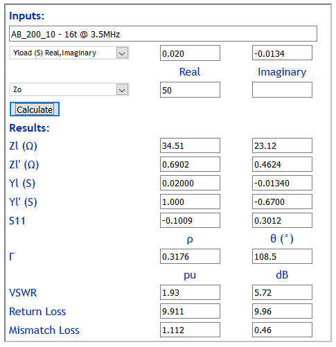
Above, the transmitter sees a VSWR of 1.93, so the balun has an Insertion VSWR of 1.93.
That doesn’t make it unusable, it just means it significantly transforms the load impedance by shunting it with an inductive reactance of around 75Ω.
The thing that does make it less suitable to most wire antenna applications is that it is a voltage balun, and voltage baluns deliver current balance ONLY on symmetric loads, and backyard wire antennas are rarely very symmetric due to the effects of nearby structures, other conductors, soil variation etc.
Simsmith model
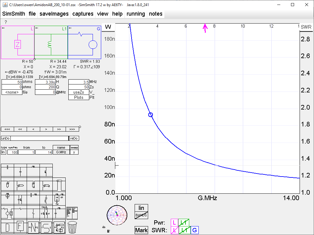
Above is a simple Simsmith model of the magetising impedance in shunt with an ideally transformed load impedance. The value of Q used is a realistic estimate, and on that basis, the core dissipation is very small, so it is unlikely to get hot. The InsertionVSWR is very high, even at 7MHz so it does not really qualify as a good broadband 1:1 voltage balun below 14MHz.
Advances over the years
Although Guanella’s design is older than Ruthroff and better suited to use with asymmetric loads, Ruthroff’s balun captured the ham application. For example, most ATUs with an integral balun use a Ruthroff 4:1 balun.
(Reisert 1978) described a Guanella balun which although it did not give details of common mode impedance, would have relatively low common mode impedance due to the core choice and turns used. The metal box and feed throughs also detract from good performance, but his application was a fairly symmetric Yagi so not very demanding. Reisert was an early if not the first published design based on Rule 500.
In the last decade or so, there has been wider recognition of the need for higher Zcm baluns to be effective in reducing common mode current, even in apparently innocuous applications.
However, people still implement baluns like the Amidon AB_200_10 balun and feed they are effective, though I cannot see any reports that give measurement data, either Zcm or Icm.
References
- Duffy, O. Baluns – Rule 500
- Guanella, G. Sep 1944. New methods of impedance matching in radio frequency circuits. The Brown Boveri Review.
- Reisert, J. Sep 1978. Simple and efficient broadband balun. Ham Radio Magazine Sep 1978 p12.
- Ruthroff C. 1959. Some broad band transformers. Proceedings of the IRE.