My article G3LNP balun explored the operation of the G3LNP 4:1 balun on a 200Ω asymmetric load and found it exhibited extreme Insertion VSWR on what should have been an ideal impedance transformation but for the asymmetric element.
The balun is in fact a Voltage Balun and cannot be expected to work properly on asymmetric loads.
A correspondent proposes that the balun probably works very well on a nearly symmetric load such as a half wave dipole.
There are two aspectes to this proposition:
- the assumption that a common half wave dipole implementation is nearly symmetric; and
- the balun works well on a nearly symmetric load.
Common dipole implementation symmetry
Whilst it might seem that a common HF dipole implementation is symmetric, the effects of nearby buildings, vegetation, structures, other antennas, soil homogeneity etc may all lead to less than ideal symmetry. W9CF discusses this and measurement in more detail at Putting a Balun and a Tuner Together.
G3LNP balun with symmetric 200Ω load at 3.5MHz
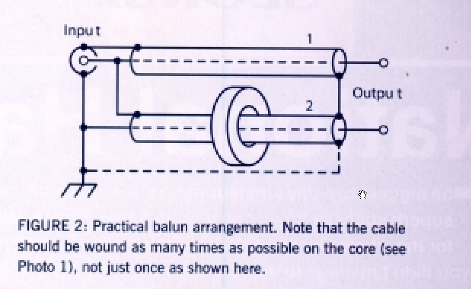
Above is the schematic supplied by G3LNP. He describes the dashed link at the bottom as optional, but uses it in his prototype so this analysis is with that link installed. The prototype used equal lengths of coax (1m PF100, an RG-6/U like coax), and the toroidal choke appears to be 8t on a T130-2 powdered iron core.
Exploration of behaviour of baluns on extreme asymmetric load often reveals whether they work properly for asymmetric loads.
Lets use a load that is a series connection of two 100Ω resistors to the top and bottom output terminals respectively and junction of the resistors grounded Such a load is very easy to analyse, there are three parallel paths from the input connector:
- the top 1m PF100 transmission line has a load of 100Ω;
- the bottom 1m PF100 transmission line has a load of 100Ω; and
- a toroidal inductor formed by the outer surface of the coax and core.
Lets solve the toroidal inductor impedance and admittance.
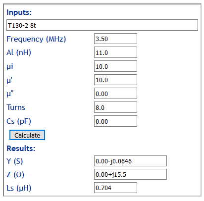
I will use RG-6/U characteristics, it is very similar to PF100.
Lets calculate the three parallel branches appearing at the input connector, we will use admittance so that we can simply sum all three branches:
- Input admittance of 1m RG-6/U transmission line has a load of 100Ω is 1.002e-2+j5.212e-4S;
- Input admittance of 1m RG-6/U transmission line has a load of 100Ω is 1.002e-2+j5.212e-4S;
- Admittance of the toroidal inductor 0.00-j0.0646S.
Total admittance is 2.004e-2-j0.06356S.
Lets calculate the input VSWR given that total input admittance.
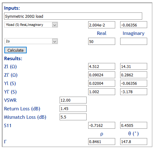
Above, input VSWR is very high at 12. The device has high Insertion VSWR on its nominal symmetric load at 3.5MHz.
The cause is the low magnetising impedance of the toroidal choke, it needs to be much higher. The design document is not very prescriptive of this component, but as can be seen, it is a critical component. A suitable medium µ ferrite core could deliver the necessary impedance.
Conclusions
A common half wave dipole is unlikely to be perfectly symmetric for many practical reasons.
This balun implementation exhibits extreme Insertion VSWR on a perfectly symmetric ‘matched’ load at 3.5MHz. The failure is mostly due to low magnetising impedance of the toroidal choke, it needs to be much higher. A suitable medium µ ferrite core could deliver the necessary impedance.
References
Putting a Balun and a Tuner Together
Why the preference for Guanella 1:1 current baluns for HF wire antennas