|
|
| OwenDuffy.net |
|
*** DRAFT ***
DK7ZB describes a balun at (Steyer nd) as part of his self titled Yagi matching scheme.
|
|
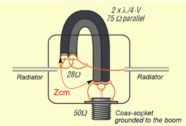
Fig 1 above is from (Steyer nd) with my added annotation of Zcm. A key parameter of a balun intended to reduce common mode current is the common mode impedance (Zcm) measured here between the shields at both ends of the device (without the DE connected).
Though Steyer proposes [a] simple solution is to ground the outer shield
in a distance of lambda/4 at the peak of the current
(a perversion of the
Pawsey stub balun), the outer surface (where common mode current might flow) of
his device is not a simple electrical quarter wave from end to end.
Steyer describes an optimal configuration for 144MHz where the line sections
are an electrical quarter wave in length in differential mode, and he recommends
line with vf of 0.82, so the line length is 300/144/4*0.82=427mm. He describes
making a loop of this two cables as shown in the picture down we get an
additional inductivity and we come closer to an electrical length of lambda/4
as an element of its operation.
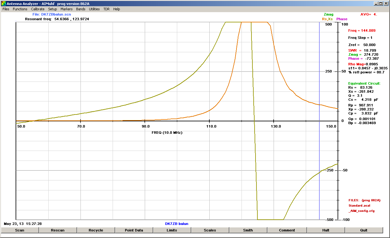
To measure Zcm, a balun of the first kind he shows was constructed with line sections as recommended of 427mm.
|
|
Fig 2 above shows a scan from AimUHF of the prototype.
There is a clear resonance around 124MHz, and common mode impedance peaks at almost 2kΩ which would make a quite effective balun at 124MHz, and for perhaps 5Mhz or so either side of that frequency.
But, this design followed Steyer's recommendations for a balun for 144MHz, some 16% higher in frequency where the actual balun offers a fairly poor Zcm of 83-j261Ω (which appears in shunt with the DE feed point).
Measurement reveals that the frequency of resonance is very sensitive to the shape of the loop, the loop tested was shaped to resemble Steyer's recommendation. If the balun was shaped to obtain resonance at 144MHz, some method of holding it in shape would be necessary to maintain that position.
The so called Ugly balun is formed by coiling a number of turns of coax to form a common mode choke.
There are many recipes, some very prescriptive, but almost never are measurements offered to support the designs.
|
|
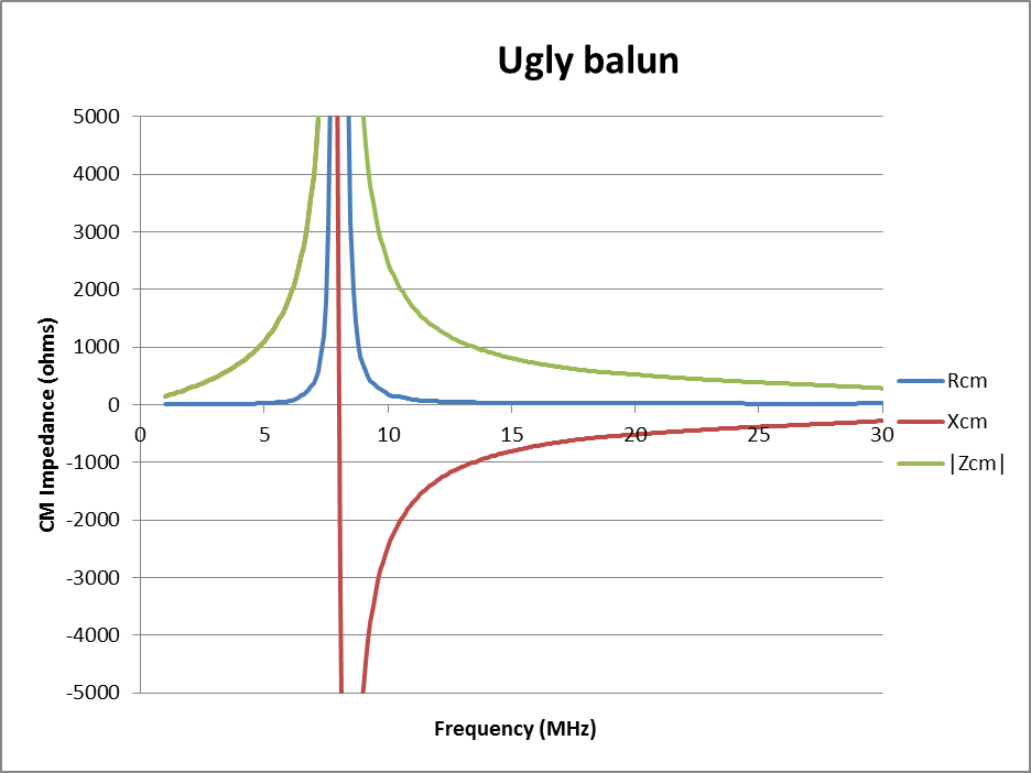
Fig 3 above shows the measured Zcm of an Ugly balun by AG6K, it has 20t of RG58 close wound on a 90mm tube.
The key characteristics of these type of baluns is a pronounced self resonance with potentially quite high Zcm near resonance and very poor Zcm away from resonance. They are essentially narrow band devices and must be carefully tuned to the desired operating frequency for good effect.
There is nothing wrong with narrow band baluns for a narrow band application (like a single band VHF Yagi), so long as it is tuned to the desired band of operation.
In the case of Fig 3, the balun would be effective on the 7MHz band, but not elsewhere on HF... though it is claimed to work from 1.8-30MHz. This is an issue with Ugly baluns, they are not broadband devices.
DK7ZB describes two variants of his balun, one with a fairly open loop (a half turn coil if you like), and the other with a full turn taken in the loop (a one and a half turn coil), but they are just variations on the Ugly balun theme, albeit adapted for VHF/UHF.
It both variants he refers to additional inductivity
of the structure
as a benefit to its operation.
In the absence of supporting measurements, the additional inductivity
is more by way of a ambit claim than a true explanation of how it works, and how
to implement one where Zcm is very high in the band of interest.
The DK7ZB match is simply a quarter wave series transformer (using two parallel coax lines to achieve a lower Zo) and a claimed balun function. The series quarter wave transformer is not novel, and the balun function performance is questionable.
(Steyer nd) does not provide any relevant measurement data to demonstrate balun effectiveness.
The DK7ZB balun integral the the DK7ZB Match is but a variant of the Ugly balun, it is a narrowband balun that must be carefully tuned to ensure that the Zcm peak does occur in the band of interest.
There are no shortage of purportedly optimised antenna designs that depend on highly symmetric DE currents where an effective balun is not part of the design. It is one of those gaps from model to real world that occurs frequently.
| Version | Date | Description |
| 1.01 | 23/05/2013 | Initial. |
| 1.02 | ||
| 1.03 | ||
| 1.04 | ||
| 1.05 |
© Copyright: Owen Duffy 1995, 2021. All rights reserved. Disclaimer.