| OwenDuffy.net |
|
The CHA250 is a 7m vertical conductor with a feed unit that accepts 50Ω coaxial cable and is claimed to have low VSWR feed from 80m to 6m. The manufacturer recommends that it be mounted at a height of about 11m.
Above is the CHA250BXII mount with matching unit (the lower black finned module).
|
|
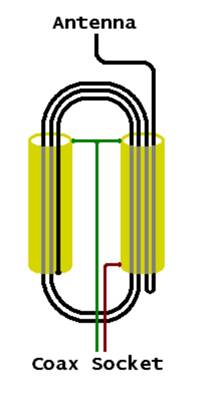
Fig 0 is from VK5ZD's dissassembly of a CHA250, see ANATOMY OF THE COMET CHA-250BXII for more images and info.It is not very clear, but the third vertical conductor from the left is outside the brass tube.
At lower HF frequencies, the magic component inside the CHA250 can be analysed as very short coaxial transmission line sections with toroidal cores on the outside to increase common mode impedance.
|
|
Fig 1 is a simplified diagram of the conductor details in the matching device. Not shown in the diagram are three ferrite sleeves fitted over each of the two tubes.
Two key properties that allow a simplified analysis:
If the current flowing to the 7m vertical tube above the feed unit is taken to be I1, it can be seen that the sum of the currents on the inner conductors of the right hand line section is 2I1 downward, and therefore the current on the inner surface of the right hand line is 2I1 upwards.
If we take the input voltage to be Vi, a current flows upwards on the outer surface of the right hand line of Vi/Zcm where Zcm is the common mode impedance of the line section, essentially the choke impedance formed the the outer surface of the line and the toroidal cores surrounding it.
Now, applying Kirchoff’s Current Law (KCL) at the node formed at the bottom of the right hand tube where the inner surface of the outer conductor, the outer surface of the outer conductor and the centre of the coax connector join, Ii=Vi/Zcm+2I1.
Looking at the left hand line section, the sum of the currents on the inner conductors is 2I1 upwards, so there is a current of 2I1 downwards on the inner surface of the outer conductor. Considering KCL at the node formed at the bottom of the left hand outer conductor, the flowing out of the node from the winding wire is I1, and the current flowing into the node on the inner surface of the outer conductor is 2I1, so the current on the outer surface of the outer conductor must be I1 out of the node (ie upwards).
Now we can treat the nodes at the top of the tubes. For simplicity, lets merge both nodes into one, so the paths and currents are:
Treating the feedline, there is Vi/Zcm+2I1 flowing upwards on the outer surface of the inner conductor, therefore Vi/Zcm+2I1 flowing downwards on the inner surface of the feedline. Given that there is I1+Vi/Zcm downwards from the feed unit to the shield, there must be I1 flowing upwards on the outer surface of the feedline / support mast.
The common mode voltage drop due to I1 in the outer surface of the left hand outer conductor is in series with the vertical radiator, so it effectively loads the radiator with a series impedance of Vi/Zcm since its construction is the same as the right hand line section.
The doubled back turn in the right hand assembly is interesting, it has no effect under this analysis. In fact, in a more detailed, more accurate analysis at higher frequencies, it is a lossy short circuit stub that introduces a very small inductive reactance and some resistance.
Because the current into the vertical is I1 and the current on the inner wire of the coax socket is 2I1, the device is a 4:1 impedance transformer, albeit non-ideal.
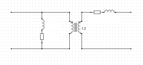 |
Fig 2 is an equivalent circuit of the 'matching device' where the
resistance and inductance shown are the components of Zcm,
and an ideal transformer with 2:1 turns ratio, or 4:1 impedance ratio.
The impedance of Zcm is frequency dependent.
In summary then, the CHA250 would appear to be an 18m vertical, fed at 7m from the top by a non-ideal, lossy 1:4 transformer.
ANATOMY OF THE COMET CHA-250BXII
© Copyright: Owen Duffy 1995, 2021. All rights reserved. Disclaimer.