 |
| OwenDuffy.net |
|
A cophased collinear array is a type of broadside array. Collinear is to mean that the elements lie on the same line, and phased, to mean that the currents in all elements are substantially in-phase, so that all elements reinforce the field strength broadside to the array.
|
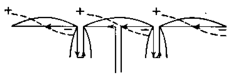
Fig 1 shows a common three element cophased collinear array from (King et al, 1945), Fig 22.3(a). The current distribution is shown with the solid curves, and the broken curves show the distribution of charge.
The phase of the current in a long wire reverses every half wave, so the half wave elements cannot be simply connected end to end, some method of causing cophased current in each half wave element is needed.
The U shaped sections in Fig 1 form such a scheme.
The U shaped sections are often know as phasing sections and a popular explanation is that the phasing sections cause a 180° phase shift due to the transit time for a wave to travel around the conductor path. This is a traveling wave explanation that seems to ignore the adjacent TL wire, and is perhaps over simplified.
Another explanation is the the U shaped sections are a quarter wave s/c transmission line stub, and that transmission line behaviour requires that the currents at the top end of each TL section are equal in magnitude and opposite in phase, which means that the currents adjacent to the stubs in the half wave elements is equal in magnitude and equal in phase having regard for direction. This explanation ignores the fact that the currents in the TL conductors need not be exactly balanced, that there may be common mode current.
(Straw et al, 2000, 8-37) also offers a brief description of operation, but no more elaborate that the above.
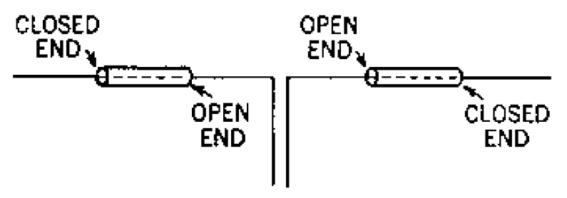 |
The explanation of the phasing sections as pure differential TL stubs is sometimes used to suggest a coaxial collinear form of the phasing section. Fig 2 shows such a coaxial implementation from (King et al, 1945) Fig 22.3(b). (King et al, 1945) notes "their operation is, however, much less satisfactory than with the open wire stubs". They also state "It is important to note that the inside diameter of the coaxial sleeves must be large compared with the diameter of the antenna and their length considerably less than &lambda/4 if a sufficient phase shift is to be achieved".
This is all a bit nebulous, giving little guidance for effective designs. Nevertheless, these designs are not uncommon.
This section explores NEC models of collinear array. The models are of half of one and a half have waves, vertically over a perfectly conducting ground. Though different to the above examples, they explore the same issues in a simpler model.
The NEC model definition language is defined in (Burke et al, 1977c).
This model uses NEC GW elements to construct the stub.
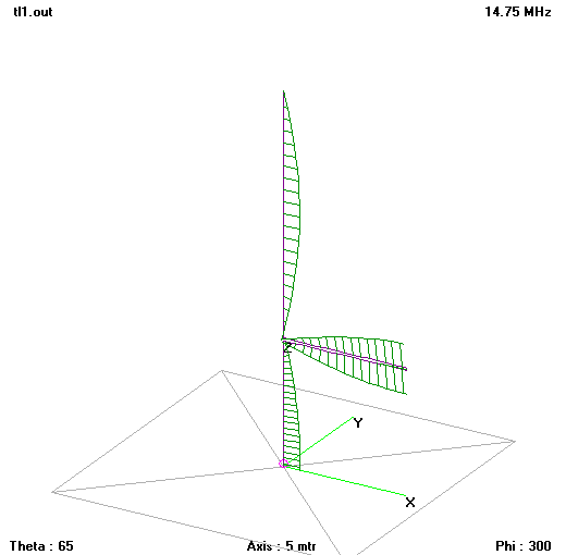 |
Fig 3 shows the structure and current (magnitude and phase) distribution near resonance. The model feed point impedance is 154+j5Ω. Download tl1.nec. The radiation resistance component of the feed point impedance is an important indicator of cophase operation, when current moment is high due to cophase currents, radiation resistance is high.
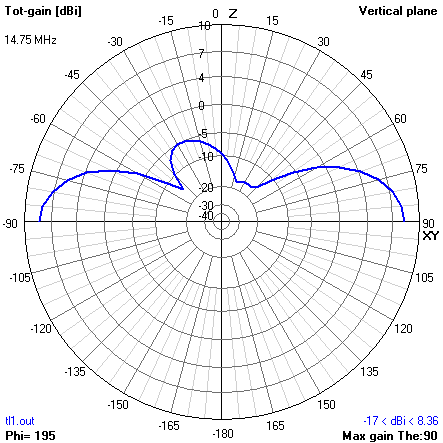 |
Fig 4 shows the radiation pattern in the vertical plane. There is some pattern asymmetry which suggests that the stub currents are not perfectly balanced. Gain is a little over 8dB, broadside to the vertical conductor.
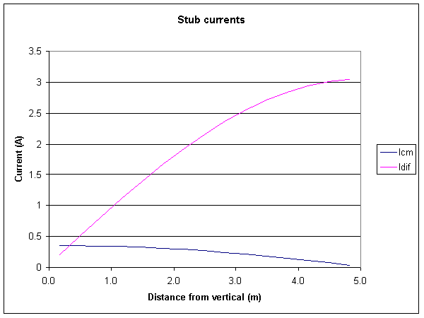 |
Fig 5 shows the model stub currents separated into differential and common mode components. Though extrapolation of the Idiff line suggests that differential current at the stub junction will be very close to zero, the common mode current is not. The common mode current could be viewed as essentially the cophase drive from the lower quarter wave to the upper half wave.
The equivalent common mode conductor being a quarter wave long and terminated in an o/c at the outboard end should offer a relatively low impedance path to common mode current at the inboard end of the stub. At the same time, the differential mode delivers a s/c quarter wave stub which offers a relatively high impedance to differential current at the inboard end of the stub.
The high differential mode impedance permits the substantial charge difference that must exist between the upper end of the lower quarter wave and the lower end of the upper half wave if they are cophased.
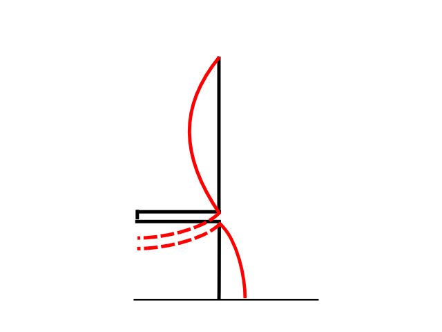 |
If an out of phase current distribution attempted to form on the vertical (see solid curve current distribution in Fig 6), the currents that would need to flow in the stub wires are shown by the dashed curves (having regard to the direction of the current and the phase change). (The sense of the dashed currents is such that they are common mode.) A common mode current maximum would need to exist at the outboard end of the stub, but that cannot happen because of boundary conditions at the end of the stub, common mode current must be zero at that point, so the mode of operation is not compatible. The common mode aspect of the stub is important in preventing establishment of out of phase current distribution on the vertical.
This model uses a NEC TL element to construct the stub.
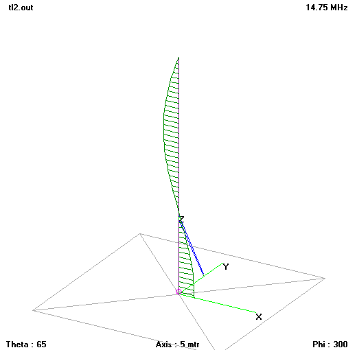 |
Fig 8 shows the structure and current (magnitude and phase) distribution near resonance. The model feed point impedance is 51.5-j15.8Ω. Download tl2.nec. Note the lower radiation resistance, it goes with the out of phase current distribution.
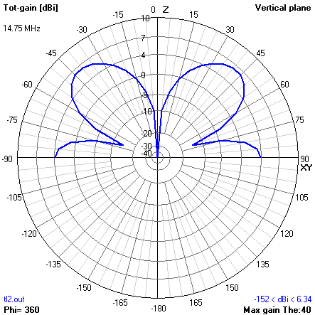 |
Fig 8 shows the radiation pattern in the vertical plane. The pattern is not that of a broadside array, evidence that the vertical currents are not cophased.
The TL model captures only the differential mode of the phasing section, and of itself, does not cause cophase operation of the vertical. The results support the proposition above that the common mode stub is important to cophase operation.
To test the theory that the stub works because of both its high impedance to differential mode current and low impedance to common mode current, a configuration was designed that delivers both high differential impedance between lower quarter wave and upper half wave, and that offers a path for common mode current that is incompatible with out of phase current distribution on the vertical.
This model uses a NEC an NT element to model a transformer to offer a high impedance to differential mode current, and low impedance to a common mode that to a GW element for the common mode stub conductor.
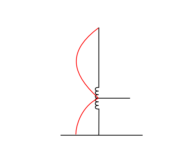 |
Fig 9 shows the configuration. The centre tapped transformer is designed to have low leakage, and high shunt impedance. It permits the substantial charge difference between the upper end of the lower quarter wave, and the lower end of the upper half wave, but offers low impedance to common mode current flowing to the horizontal conductor due to flux cancellation. It is modelled by the NT card:
NT 1 15 2 1 0 -0.1 0 0.0999 0 -0.1
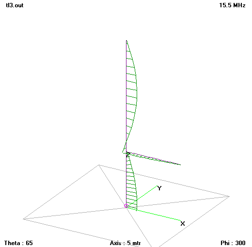 |
Fig 10 shows the structure and current (magnitude and phase) distribution near resonance. The model feed point impedance is 154+j15.1Ω. Download tl3.nec. Radiation resistance is high, consistent with cophase current distribution.
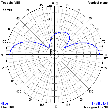 |
Fig 11 shows the radiation pattern in the vertical plane. There is some pattern asymmetry due to small common mode current on the horizontal conductor.
This model uses an NEC NT element to model the transformer, which is essentially now just a high impedance inductor.
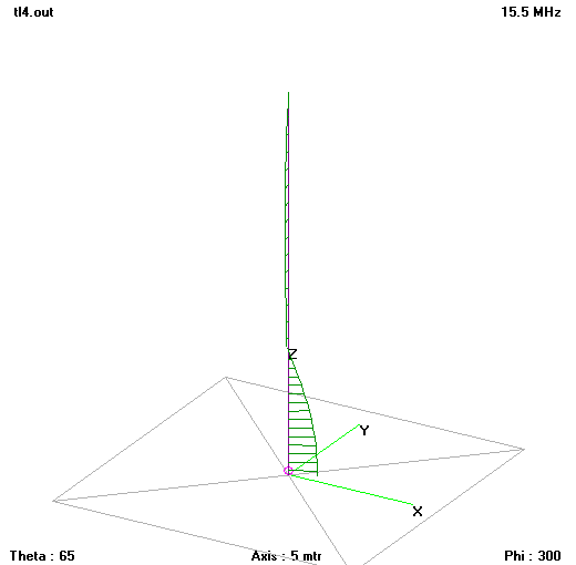 |
Fig 12 shows the structure and current (magnitude and phase) distribution near resonance. The model feed point impedance is 36+j23Ω. Download tl4.nec. There is little current on the upper half wave, and it is not in phase with the lower quarter wave, and radiation resistance is low due to reduced current moment.
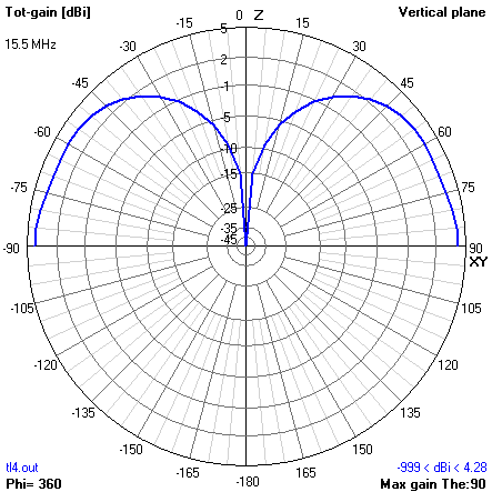 |
Fig 13 shows the radiation pattern in the vertical plane. Though the pattern is broadside to the wire, it is so because essentially, only th lower quarter wave is active, and gain is well down on cophased operation of the whole vertical.
Configurations with an insulating gap where the transformer is in this case, or a high inductance coil, or a parallel resonant circuit behave similarly, permitting out of phase current distribution, low radiation resistance, low gain, and poor pattern. The lack of a common mode path to suppress the undesired mode is the reason why all of these configurations are not equivalent to Figs 1 and 3.
As noted earlier, there are designs where the phasing stub is implemented coaxially in line with the radiator elements, see Fig 2. It is an elegant and simple construction that is appealing, but it would appear to be fundamentally different from Figs 1 and 3 in that whilst it is relatively easy to implement the differential mode TL with the coaxial elements, the common mode stub does not exist, and its role in suppressing out of phase operation of the elements is lost.
Note that not all antennas called Coaxial Collinear Phased Arrays are constructed as per Fig 2, and this discussion relates ONLY to those with phasing sections / stubs constructed as per Fig 2.
Some would argue that the inability of NEC to demonstrate cophase excitation using TL representation of the coaxial stub is a failure of NEC, but the development above suggests that the absence of the stub common mode path of such length that is suppresses out of phase excitation is the real problem, the coaxial collinear stub design lacks a critical element.
(Basilotto 2003) says of his antenna that uses coaxial collinear elements "The mystery part of the antenna comes from the fact that it is difficult, if not impossible, to model and explain why the antenna works as well as it does" though he doesn't really document its actual performance.
(Duffy 2009) shows a solution for the W5GI Mystery Antenna using NEC to model the conductors with NEC LD elements to insert a load corresponding to the impedance seen looking into the coaxial stubs.
| Version | Date | Description |
| 1.01 | 30/03/09 | Initial |
Use at your own risk, not warranted for any purpose. Do not depend on any results without independent verification.
© Copyright: Owen Duffy 1995, 2021. All rights reserved. Disclaimer.