 |
| OwenDuffy.net |
|
Tom Rauch (W8JI) performed an experiment to measure the delay through a practical antenna loading coil, the experiment was reported at (Rauch 2006).
The experiment was performed in the context of a long running discussion in various online fora, regarding the phase shift of current flowing at one end of such a coil relative to the other, and whether or not a lumped constant model of the coil is adequate for various purposes.
Rauch measured a coil of the following dimensions: 100 turns, 254mm long, 52mm diameter. He measured Q of 290 at 4MHz.
|
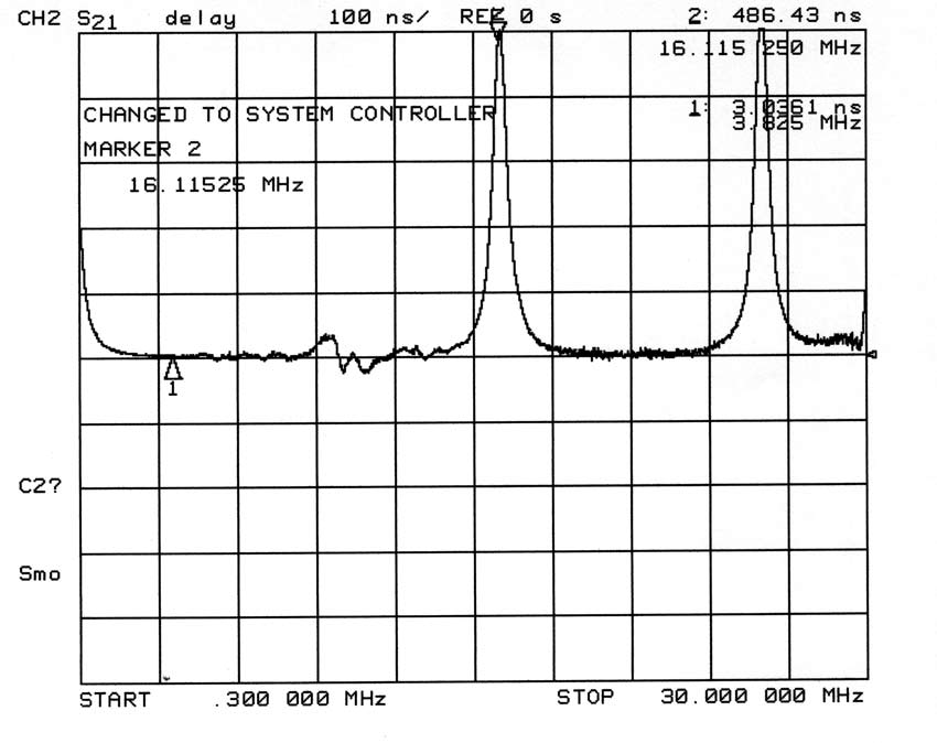
Fig 1 is from (Rauch 2006). It appears to be a S21 group delay plot taken with the coil between the tx and rx ports of a VNA.
Rauch draws the following conclusions:
On 80-meters, and actually over a fairly wide frequency range, time delay is about 3nS. 3nS is equivalent to 3.06 feet of distance. We know one foot is occupied by the test fixture connections, so the ten-inch long inductor appears to be about two feet long, so far as current propagation delay.
How does the current travel through the inductor so fast? After all, the wire is about 53 feet long.
At first this seems impossible, but the answer is actually quite obvious. Time-varying current gives rise to time-varying magnetic flux. This magnetic flux, since conductor spacing is close and distance very small, links each turn very tightly to the adjacent turn. The rapidly changing magnetic flux causes charges to move in the adjacent conductor. The changing magnetic field couples through all the close-spaced turns with very little time delay. It is this magnetic flux coupling that provides the primary mechanism for energy transfer through this inductor, and the path is much shorter than the circuitous and much longer path along the conductor.
The above measured data, shown in the screen capture above, shows time delay of current is very close to zero.
Simulation of Rauch's experiment provides a more detailed base for discussing the issues arising.
We might approximate the test configuration as a pi network, the inductance and associated series resistance in series from input to output terminal, and a small capacitance (Cs) from each terminal to ground to capture the effect of stray capacitance.
Without seeing the details of Rauch's experiment, it is not possible to be prescriptive about a value for the stray capacitance. However, in a well constructed experiment, it is probably in the region of several pF for each the the equivalent capacitances, lets assume 3pF for each of the capacitors.
Calculating the inductance of the coil using Wheeler's Continuous Formula, L=96µH.
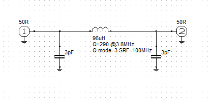 |
Fig 2 shows the simulation circuit. So, the circuit (including a 50+j0Ω load to represent the VNA rx port) can be solved for S21 at a range of frequencies, including calculation of S21 group delay.
Group delay is defined as the negative of the slope of the phase/frequency response:
Group delay does not imply any particular absolute delay.
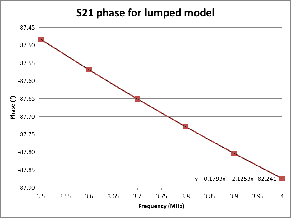 |
Fig 3 shows the calculated phase of S21 over the range 3.5 - 4MHz. The curve is not a perfect straight line, but is a very good fit to a second order polynomial. We can calculate the slope of the line from the curve fit, and calculate group delay.
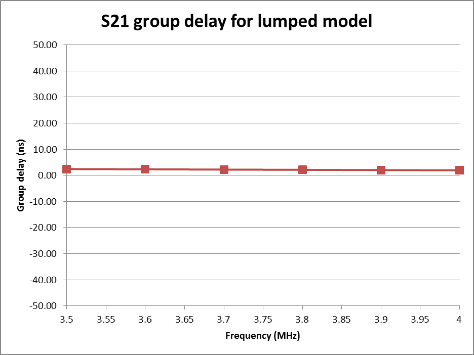 |
Fig 4 shows the calculated group delay of S21 over the range 3.5 - 4MHz at the same vertical scale as Fig 1. The group delay is not very sensitive to small changes in the assumed Cs.
So, the simulation gives S21 group delay similar to the statistic of the same order as that offered by Rauch, if plotted over this range is will be an almost horizontal line at just over 2ns.
The simulation also allows calculation of the phase of the current at the output end compared to the input end of the network.
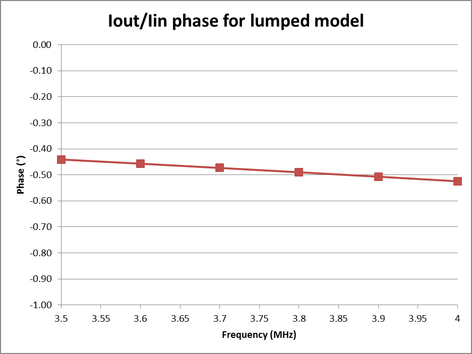 |
Fig 5 shows the calculated phase of Iout/Iin. The phase angle of Iout/Iin is around 0.5° for the values used, and it is quite sensitive to the value of Cs. For Cs=10pF, the phase angle of Iout/Iin is around 2.5° which implies an equivalent absolute time delay of around 1.8ns. These phase shifts are specific to the simulation circuit, they are sensitive the the assumed stray capacitance and the 50Ω load on 'output end' the coil.
The results are not simply extensible to the same coil in the middle of a loaded vertical radiator.
| Version | Date | Description |
| 1.01 | 05/03/2012 | Initial |
| 1.02 | ||
| 1.03 | ||
| 1.04 | ||
| 1.05 |
© Copyright: Owen Duffy 1995, 2021. All rights reserved. Disclaimer.