| OwenDuffy.net |
|
Users of T match ATUs are often interested in estimating the efficiency of the ATU. This article explores a simple loss model for the highpass T match. The model does not include a balun, balun losses are additional and can be quite high in the case of voltage baluns deployed in the region of a voltage maximum.
A simple loss model is to consider the capacitors to be lossless, and the only loss therefore to be in the inductor. This is not a bad approximation as the loss in practical ATUs with air spaced capacitors is almost entirely in the inductor. The model assumes Q of the inductor is constant for all values of inductance. In practical variable inductors, Q does vary with inductance, but over the narrow range of inductance used on one band, the assumption is reasonable.
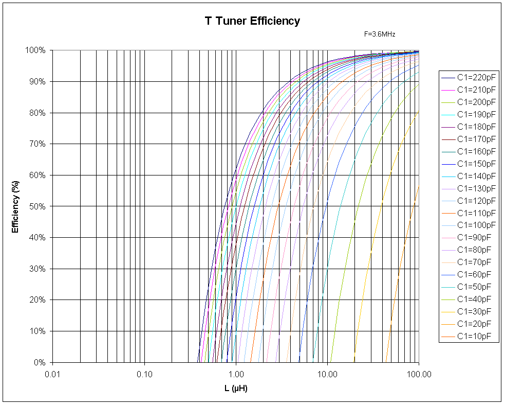
With these simplifications, the efficiency of the ATU can be estimated from knowledge of C1 (the input capacitor), L and intrinsic Q of L. In this analysis, C1 is taken to have a maximum of 220pF (as used in many popular ATUs), and Qli is taken as 100. The analysis is performed at 3.6MHz, as efficiency is poorest at lower frequencies.
The graph above plots ATU efficiency against L for various values of C1. (Click on the image and zoom in for a larger image.)
After adjusting an ATU, if you consult the chart, you can get a good estimate of efficiency.
For example, MFJ’s 949E has 220pF caps, and switched inductors. Lets assume that Q of the inductors is 100. Lets say loading a 50+j0Ω load that the lowest inductor tap that works is 6ÁH, and C1=175 will give the match. If you look the graph up, you get an efficiency of 90%… not too bad.
Now lets try a G5RV fed with just 10m of 400Ω ladder line. Load Z is about 8+j32. Lets say the lowest inductor tap is 6ÁH, and C1=105pF will give the match. If you look the graph up, you get an efficiency of about 73%… not so good, especially when the line efficiency of 70% if factored in.
© Copyright: Owen Duffy 1995, 2021. All rights reserved. Disclaimer.